24 Rockwell Automation Publication 20Y-TG001C-EN-P - April 2017
Chapter 2 Active Front End System Overview
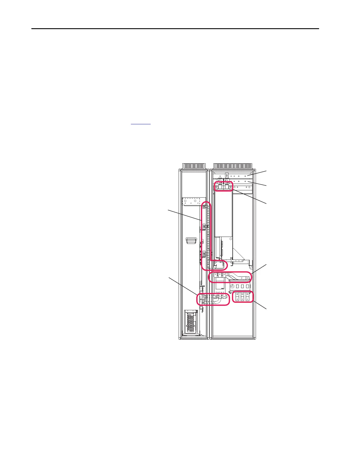
Bus Bar Locations
There are several sets of bus bars in the AFE Frame 10 system that connect
main system components:
• Bus bars between input disconnect (Q0) and MCCB (Q1)
• Bus bars between MCCB (Q1) and the LCL filter (L1)
• Bus bars between the LCL filter (L1) and AFE power structure (U1)
• Bus bars between the AFE power structure (U1) and DC bus bars
Figure 6
shows the bus bar locations.
Figure 6 - AFE Frame 10 Bus Bar Locations in IP21 Rittal Enclosure
DC+ bus bar
DC- bus bar
DC bus bars between AFE
Power Structure (U1) and DC
fuses
AC bus bars between Input
Disconnect (Q0) and Motor-
Controlled Circuit Breaker
(Q1)
AC bus bars
Between Motor-Controlled
Circuit Breaker (Q1)
and LCL Filter (L1)
AC bus bars
Between LCL Filter (L1)
and AFE Power Structure (U1)
AC Input bus
bars
Front View
(shown with enclosure doors removed)
 Loading...


