Rockwell Automation Publication 20Y-TG001C-EN-P - April 2017 33
Component Test Procedures Chapter 3
Perform Gate Driver Board
Resistance Measurements
To perform the gate driver board resistance measurements, follow these steps.
1. Remove power from the AFE.
See Remove Power from the AFE on page 37
.
2. If present, remove the protective barriers.
See Remove AFE Protective Barriers on page 44
.
3. Remove the protective front cover and terminal cover from the power
structure.
See Remove Protective Covers from the Power Structure on page 46
.
There is one gate driver board.
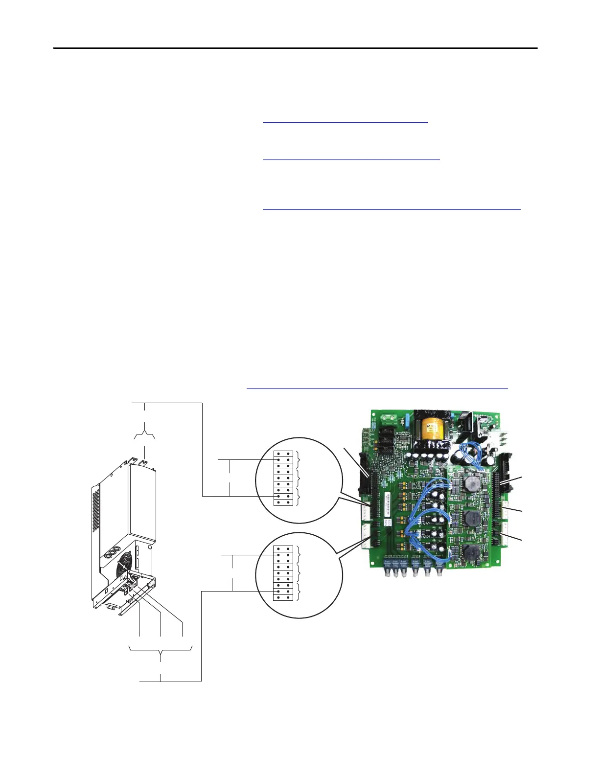
4. Measure the gate interface resistance for each (U, V, and W phase)
output power transistor:
• The resistance from each ignition pin to the branch emitter pin
(connectors X28 and X29) is approximately 166 Ω.
• The resistance from the X28 branch emitter pin to the same branch
output power terminal (U/T1, V/T2, and W/T3) is approximately
0.5 Ω.
• The resistance from the X29 branch emitter to the same branch DC-
bus terminal is approximately 0.5 Ω.
If any of the gate interfaces fails this test, replace the power module. See
Remove the Power Module from the Power Structure on page 55
.
Gate Interface for
U, V, or W High (H)
Gate Interface for
U, V, or W Low (L)
X29
X30
X22
X23
X24
Emitter
Extinguishing
Ignition
Approx.166 ohms
Approx. 0.5 ohms
Approx.166 ohms
Approx. 0.5 ohms
U/T1V/T2W/T3
DC-
X28
Emitter
Extinguishing
Ignition
Important: Connectors X22 and X23 are connected in
parallel with connectors X28 and X29 respectively and,
therefore, do not have to be tested.
 Loading...


