Rockwell Automation Publication 20Y-TG001C-EN-P - April 2017 37
AFE Power Structure Component Section Chapter 4
Remove Power from the AFE
To remove power from the AFE, follow these steps.
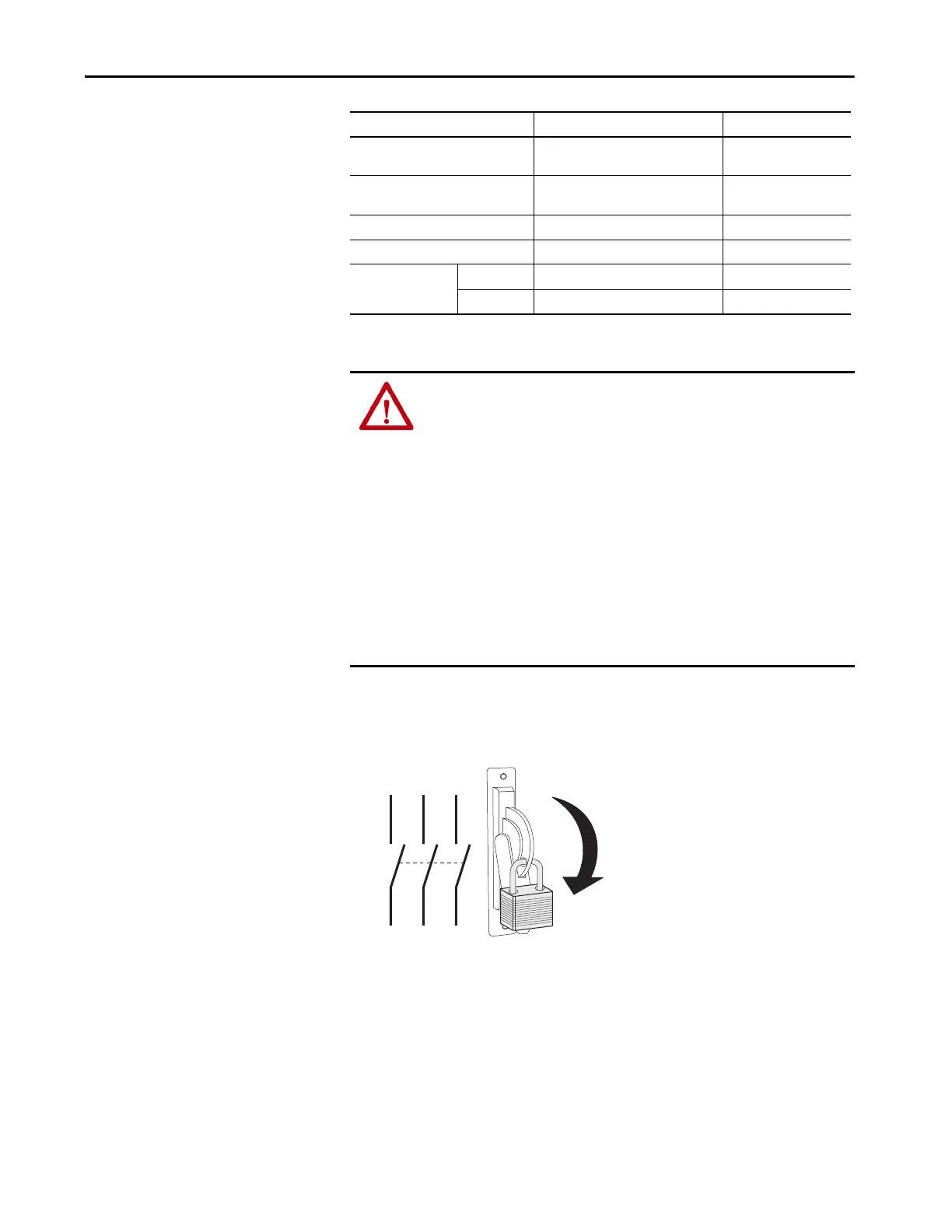
1. Turn off and lockout input power.
2. Wait 5 minutes.
3. Verify that there is no voltage at the AFE input power terminals.
4. Check the DC bus voltage between the +DC and -DC terminals,
between the +DC terminal and the chassis, and between the -DC
terminal and the chassis.
The voltage must be zero for all three measurements before proceeding.
Motor output terminals on power
structure
M8 x 20 hexagonal screws 20 N•m (177 lb•in)
Power structure output terminals (U, V,
W)
M8 x 20 hexagonal screws 14 N•m (124 lb•in)
Power structure block (mounting) M10 x 12 hexagonal screws 20 N•m (177 lb•in)
Power structure DC bus input terminals M6 x 16 Pozidriv screws 4 N•m (35 lb•in)
Protective covers on
power structure
Front M5 x 10 Pozidriv screws 3 N•m (27 lb•in)
Terminal M5 x 16 Pozidriv screws 3 N•m (27 lb•in)
Item Hardware Final Torque
ATTENTION: To avoid an electric shock hazard, verify that the voltage on the
bus capacitors has discharged completely before servicing. Check the DC bus
voltage between the +DC and -DC terminals, between the +DC terminal and
the chassis, and between the -DC terminal and the chassis. The voltage must
be zero for all three measurements.
Remove power before you make or break cable connections. When you remove or
insert a cable connector with power applied, an electric arc can occur. An electric
arc can cause personal injury or property damage by these actions:
• Sends an erroneous signal to the system field devices, which causes
unintended machine motion.
• Causes an explosion in a hazardous environment.
Electrical arcing causes excessive wear to contacts on both the module and its
mating connector. Worn contacts can create electrical resistance.
L1 L2 L3
O
I
 Loading...


