Rockwell Automation Publication 20Y-TG001C-EN-P - April 2017 31
Component Test Procedures Chapter 3
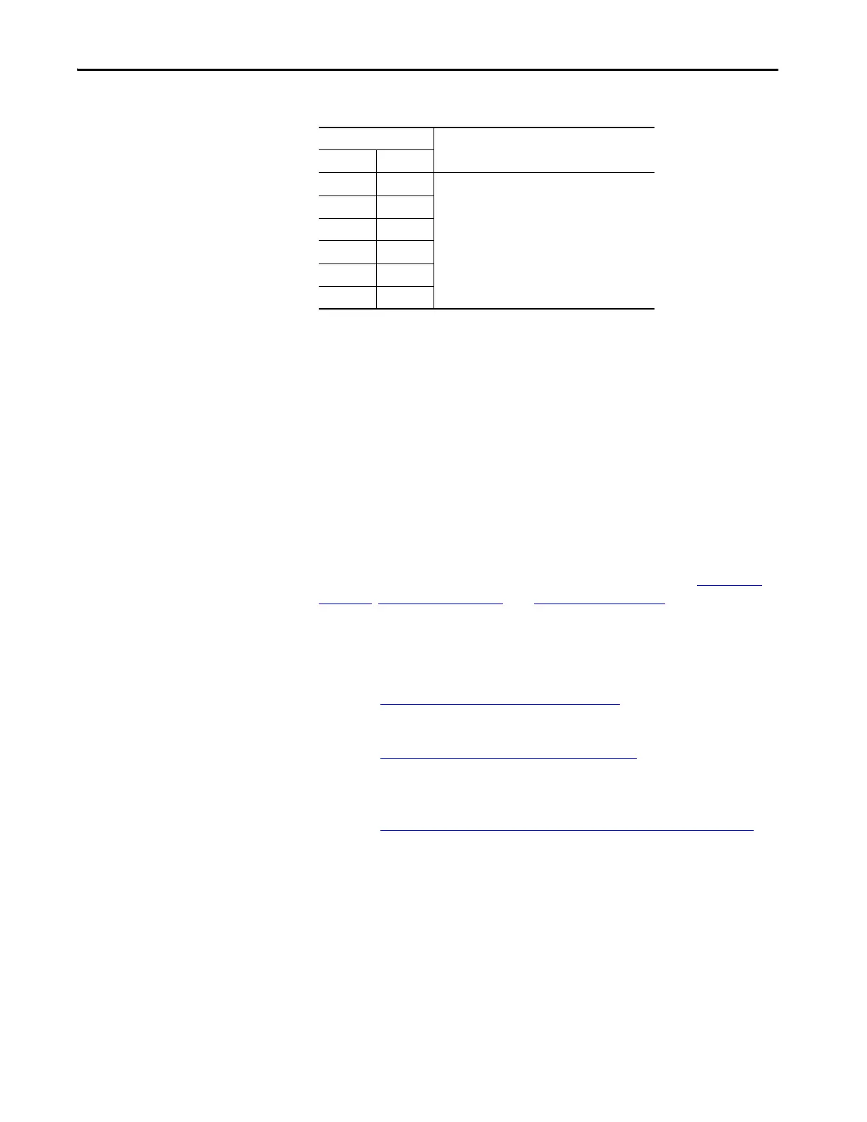
Table 3 - Reverse Biased Diode Tests on Power Structure
If the AFE fails any of these measurements, replace the power module in
the power structure, or the complete power structure. To replace the
components, follow one of these options:
• Contact your local representative to schedule on-site services.
• Contact your local representative to make arrangements to return the
power structure to the factory for repair by remanufacturing services.
• For an AFE not covered under factory warranty, a customer has the
option of repairing the power structure using procedures that are
described in this manual.
Check Fiber-optic
Connections
Damaged or improperly connected fiber-optic cables can cause apparent gate
driver board malfunctions. For fiber-optic cable connections, see Tabl e 9 on
page 113, Table 10 on page 114, and Figure 35 on page 115.
To check the fiber-optic connections, follow these steps.
1. Remove power from the AFE.
See Remove Power from the AFE on page 37
.
2. If present, remove the protective barriers.
See Remove AFE Protective Barriers on page 44
.
3. Remove the protective front cover and terminal cover from the power
structure.
See Remove Protective Covers from the Power Structure on page 46
.
4. Locate the gate driver board on the front of the power structure
(right-side enclosure).
Meter Leads Nominal Meter Reading
+-
U/T1 DC- Meter displays ‘.0L’ (zero load)
V/T2 DC-
W/T3 DC-
DC+ U/T1
DC+ V/T2
DC+ W/T3
 Loading...


