Rockwell Automation Publication 20Y-TG001C-EN-P - April 2017 51
AFE Power Structure Component Section Chapter 4
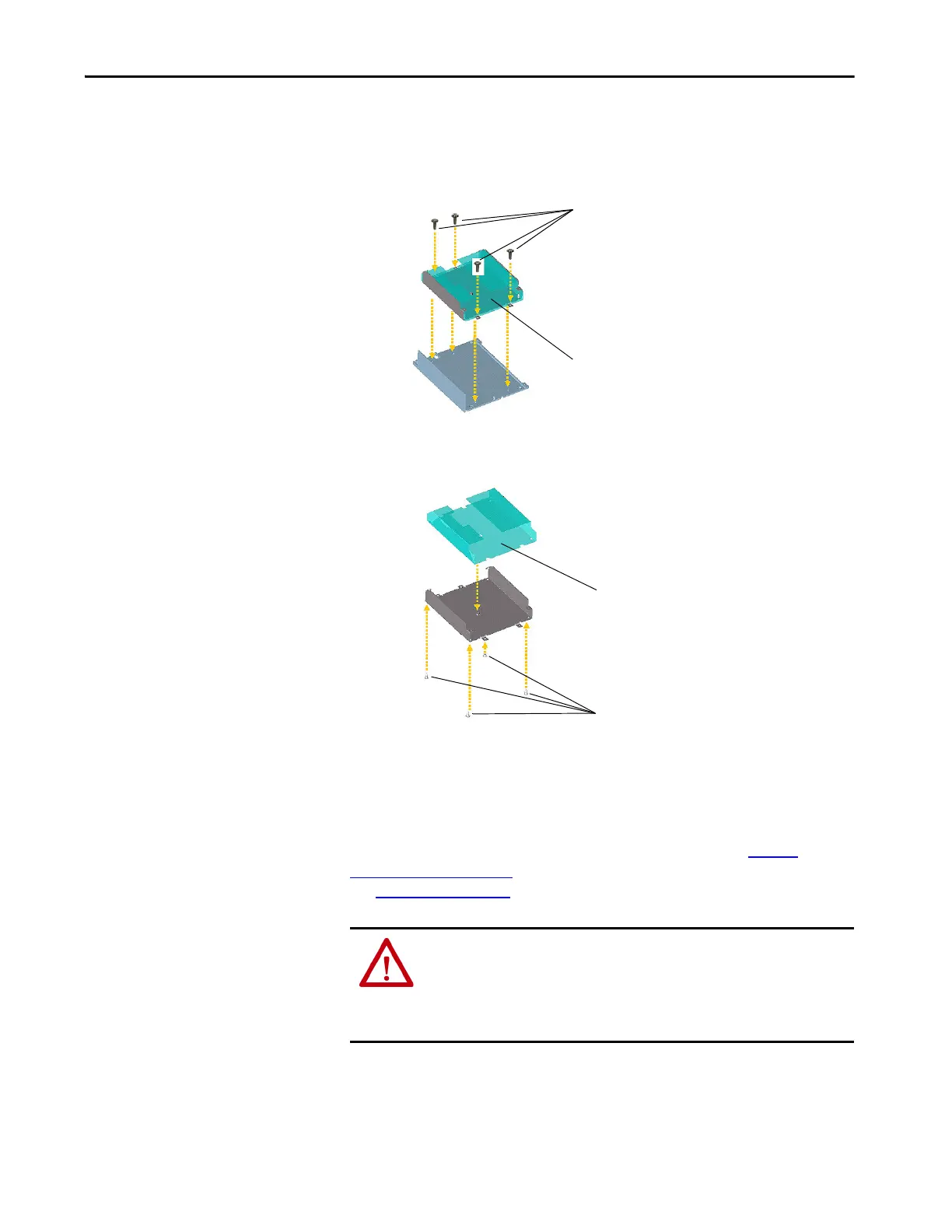
If the plastic insulator requires replacement, follow these steps.
a. Remove the four screws that secure the board holder to the metal
frame, and remove the metal frame and insulator.
b. Carefully remove the four fasteners that secure the insulator to the
metal frame, and remove the insulator.
c. Replace the insulator.
Install the ASIC Circuit Board
Install the ASIC circuit board in reverse order of removal. See To rq u e
Specifications on page 36. Reconnect cables and jumpers to the ASIC board.
See Figure 13 on page 91
.
ATTENTION: The sheet metal cover and mounting screws on the ASIC circuit
board that is on the power structure are energized at (-) DC bus potential high
voltage. Risk of electrical shock, injury, or death exists if someone comes into
contact with the assembly. Verify that the -DC bus wire is properly connected
to the ASIC chassis cover.
Remove Screws
Remove Metal Frame and Insulator
Remove Insulator
Remove Fasteners
 Loading...


