50 Rockwell Automation Publication 20Y-TG001C-EN-P - April 2017
Chapter 4 AFE Power Structure Component Section
8. Disconnect the X9 terminal block and the X15 terminal connectors.
9. Disconnect the X3, X4, X5, X6, and X10 cables from sockets on the
front of the ASIC board, and set them aside.
10. Remove the four screws that secure the ASIC assembly to the power
structure and remove the ASIC assembly.
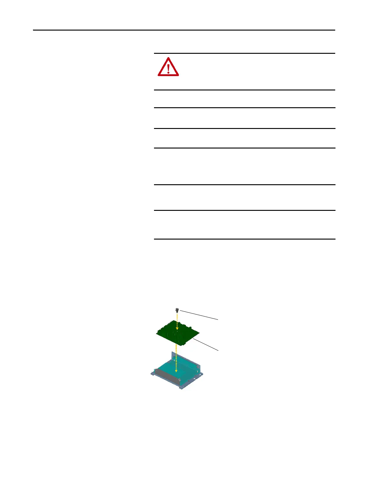
11. Remove the screw and detach the four plastic standoffs that secure the
ASIC board to the ASIC chassis, and remove the ASIC board.
ATTENTION: Hazard of permanent eye damage exists when using
optical transmission equipment. This product emits intense light and
invisible radiation. Do not look into fiber-optic ports or fiber-optic
cable connectors.
IMPORTANT When mishandled, the ability of fiber-optic cables to transmit data
is greatly diminished.
IMPORTANT The minimum inside bend radius for fiber-optic cable is 25.4 mm
(1 in.). Any bends with a shorter inside radius can permanently
damage the fiber-optic cable. Signal attenuation increases with
decreased inside bend radii.
IMPORTANT When replacing the existing ASIC board with a new board, the X9
and X15 connectors must be transferred and connected to the new
board before installation.
Remove Screw
Remove ASIC Circuit Board from Chassis
 Loading...


