Rockwell Automation Publication 20Y-TG001C-EN-P - April 2017 93
Schematic Diagrams Appendix B
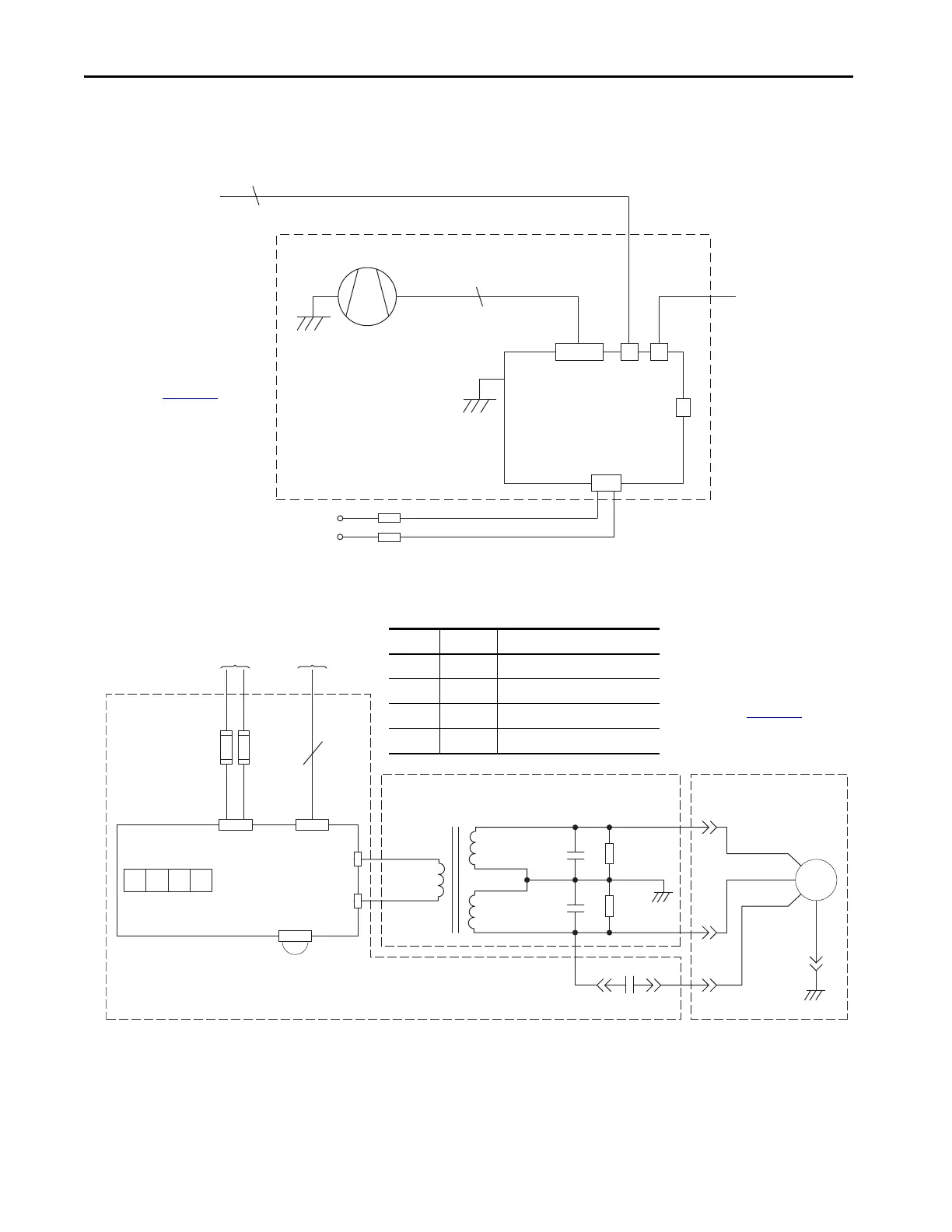
Frame 10 Power Structure
Main Fan Connections
Figure 15 - DC Fan Power Supply (all AFEs—in IP20 2500 MCC Style or IP21 Rittal enclosure—
January 2013 and later)
Figure 16 - AC Fan Power Supply (only AFE Power Structure in IP21 Rittal enclosure—
December 2012 and earlier)
DC Main Fan
To X51 on the
LCL Filter Power
Supply Circuit Board
To ASIC
Circuit Board X11
(Fan Control)
Isolated 48V DC Power
Supply Circuit Board
3
4
X81 X8 X3
X2
DC+
DC-
X82
Fan Module
For more details, see the
PowerFlex 700S, 700H, and
700AFE Drive Fan Systems
Installation Instructions,
publication PFLEX-IN029.
X8
F2
X2
4
Fan Frequency
Converter
+–
O
S1-1
O
S1-2
On
S1-3
O
S1-4
S1 - Setup Switch
F1
From Power
Board X10
From ASIC
Board X11
M1
Main Fan
Brown
Black
Blue
M
Black 6
2.2 µF
2.2 µF
7 µF
Black 5
Black 4
Black 3
Black 2
Black 1
X4
X5
10 MW
10 MW
Yellow/
Green
Fan Area
Area Under Main Power Terminal Strip
Area Under Fan Power Supply Plate
X3
Switch Setting To indicate the following:
S1 Off 50 Hz fan motor frequency
S2 Off 220V AC motor voltage
S3 On 230V AC motor voltage
S4 Off Not used
For more details, see the
PowerFlex 700S, 700H, and
700AFE Drive Fan Systems
Installation Instructions,
publication PFLEX-IN029
.
 Loading...


