Rockwell Automation Publication 20Y-TG001C-EN-P - April 2017 23
Active Front End System Overview Chapter 2
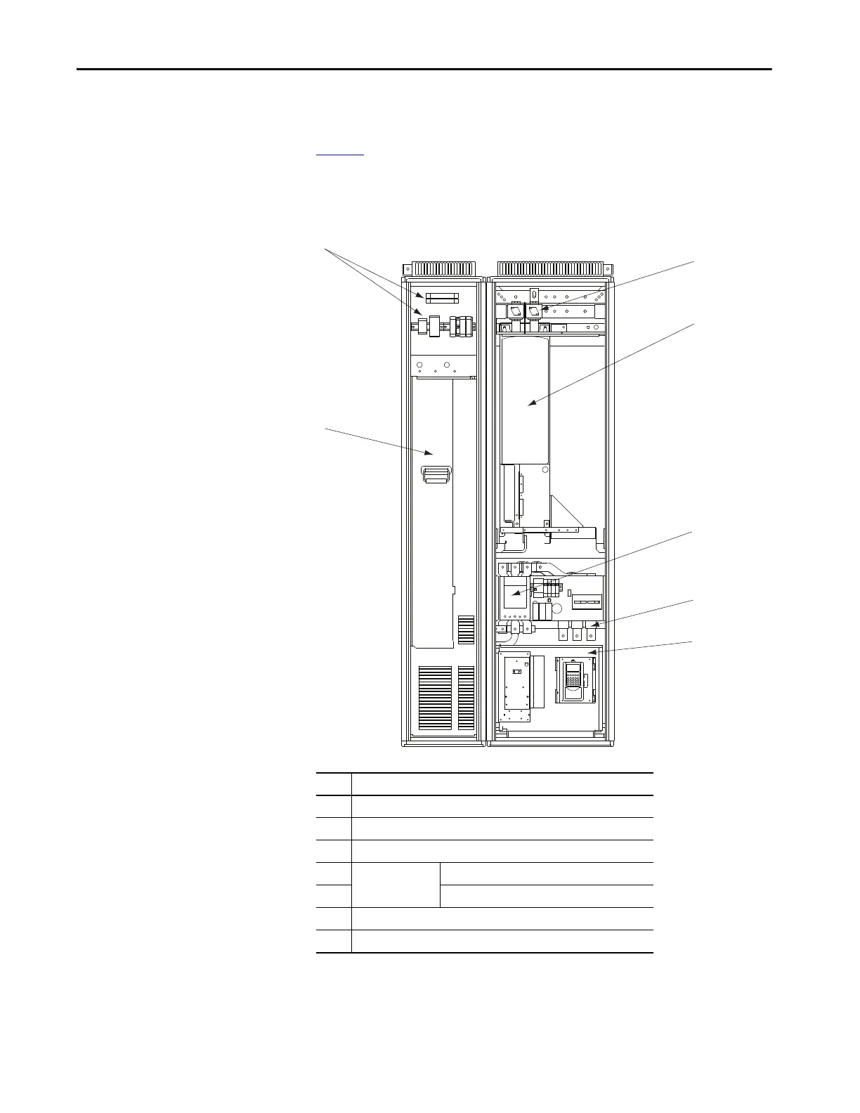
Main Component Locations
Figure 5 shows the main components of the AFE Frame 10 system in an IP21
Rittal enclosure.
Figure 5 - AFE Frame 10 Main Component Locations in IP21 Rittal Enclosure
1
2
3
7
4
5
6
Front View
(shown with enclosure doors removed)
Item Description
1 Precharge circuit and precharge resistors (R6.1 and R6.2)
2 LCL filter (L1)
3 Active Front End power structure (U1)
4 AC line switchgear Motor-controlled circuit breaker (Q1)
5 Input disconnect (Q0)
6 AFE control assembly (shown with user-installed HIM)
7 DC fuses (F2.1 and F2.2)
 Loading...


