Rockwell Automation Publication 20Y-TG001C-EN-P - April 2017 39
AFE Power Structure Component Section Chapter 4
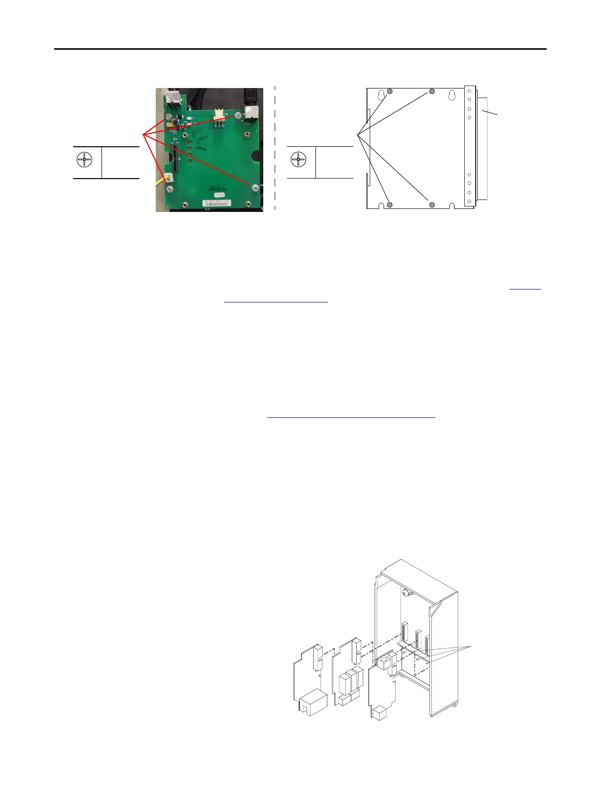
Install the DPI Interface Assembly
Install the DPI interface assembly in the reverse order of removal. See To rq u e
Specifications on page 36.
Remove the I/O Circuit Boards and Control Board
To remove the I/O circuit boards and control board, follow these steps.
1. Remove power from the AFE.
See Remove Power from the AFE
on page 37.
2. For an AFE in an IP20 2500 MCC Style enclosure, open the control box
and carefully unplug the DPI cable and any I/O cables.
For an AFE in an IP21 Rittal enclosure, open the enclosure that contains
the control and I/O circuit boards and carefully unplug the DPI cable
and any I/O cables.
3. Remove the I/O boards from the control board and enclosure.
Note the order of the boards and the keys that help to prevent placement
of boards in incorrect slots.
P1
0.9 N•m
(8 lb•in)
Mounting Screws
Door (with DPI
interface board
and HIM) in
open position.
For AFE in IP21 Rittal
Enclosure
For AFE in IP20 2500 MCC
Style Enclosure
P1
0.9 N•m
(8 lb•in)
Mounting Screws
Important: Do not remove the
enclosure cover from the control frame.
For clarity, the enclosure is shown
without the cover.
Keys
 Loading...


