Rockwell Automation Publication 20Y-TG001C-EN-P - April 2017 61
AFE Power Structure Component Section Chapter 4
24. Remove the M4 x 8 screws that secure the power module to the power
structure.
25. Remove the power module.
Install the Power Module on the Power Structure
Install the power module in reverse order of removal. See Torque Specifications
on page 36.
Remove the Power Structure DC Bus Capacitors
1. See Remove the Power Module from the Power Structure on page 55,
and perform step 1
through step 21.
Do not perform steps step 24
and step 25—removal of the power
module is not necessary to replace the DC bus capacitors.
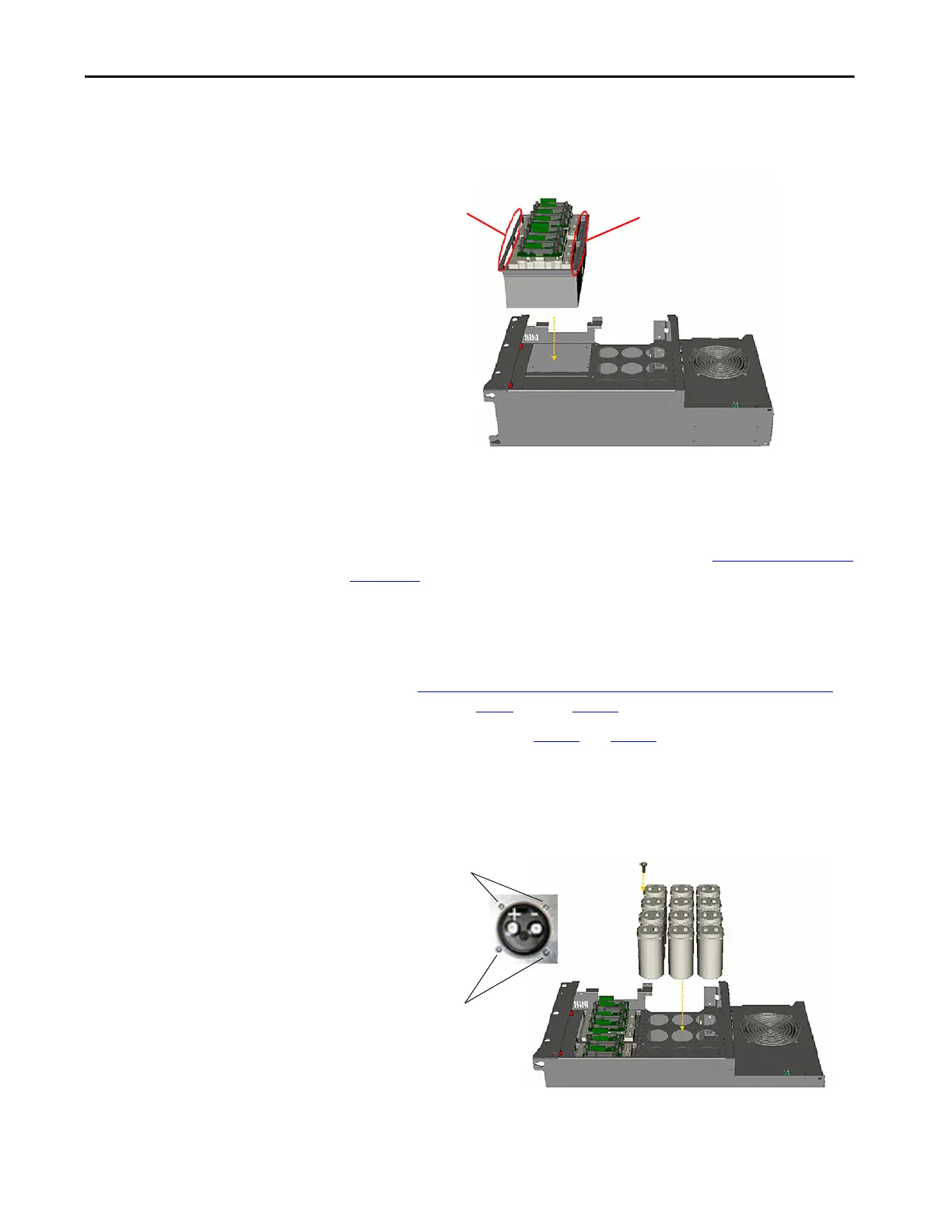
2. Note the polarity of the capacitors.
3. Remove the four M4 x 8 screws that secure the capacitor to the power
structure.
4. Remove the capacitor.
Remove Screws
Remove Screws
Remove Screws
Remove Screws
 Loading...


