60 Rockwell Automation Publication 20Y-TG001C-EN-P - April 2017
Chapter 4 AFE Power Structure Component Section
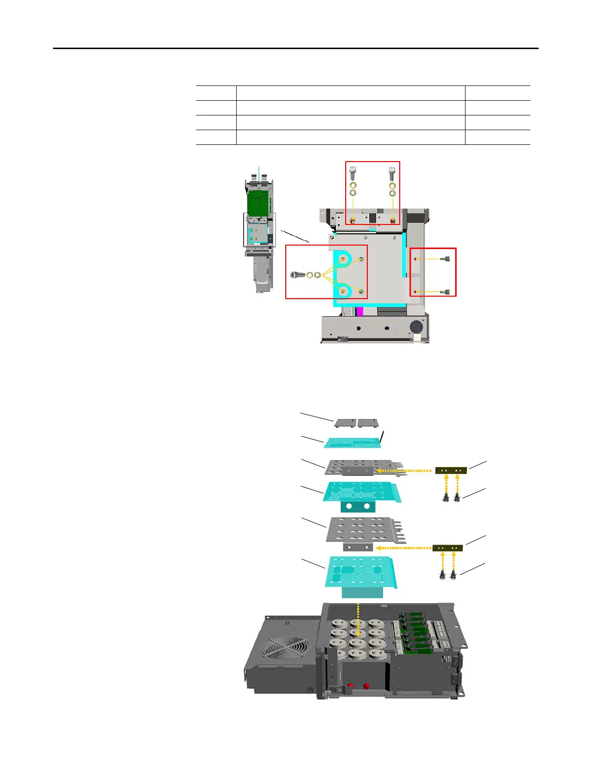
23. Remove the connective DC bus bars and insulators.
Tightening torque for reassembly is 4 N•m (35 lb•in).
Location Fasteners Torque
1 M10 x 25 hexagonal screws, M10 spring washers and M10 washers 8 N•m (70 lb•in)
2 M8 x 25 hexagonal screws, M8 spring washers and M8 washers 8 N•m (70 lb•in)
3 M6 x 12 screws 4 N•m (35 lb•in)
1
2
3
690V AFE
Power Structure
Shown
Bus Bar
Bus Bar
Bus Bar
Insulator
Insulator
Insulator
Remove
Screws
Remove
Screws
Metal Plate
Metal Plate
Remove all screws holding bus bars and
insulators to AFE frame.
 Loading...


