22 Rockwell Automation Publication 20Y-TG001C-EN-P - April 2017
Chapter 2 Active Front End System Overview
AFE in IP21 Rittal Enclosure
Main Component Sections
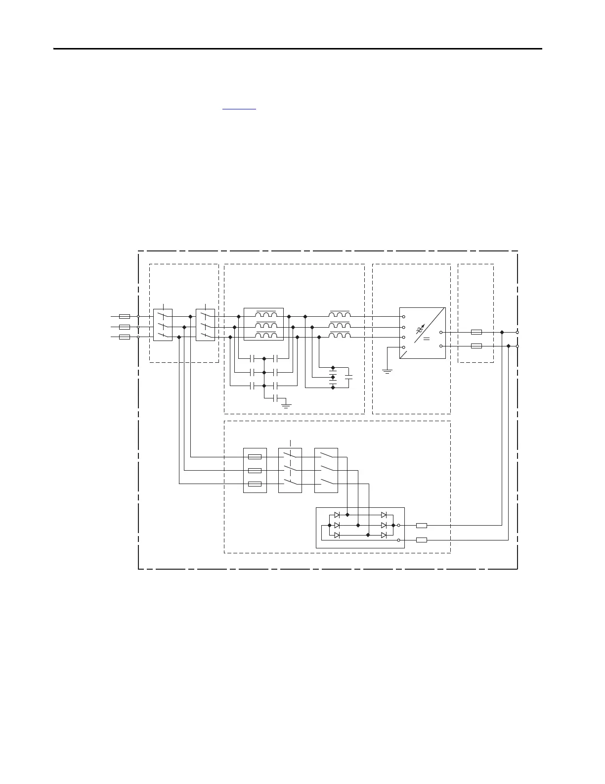
Figure 4 shows a basic one-line diagram for an AFE system in an IP21 Rittal
enclosure. The main component sections consist of the following items:
• AC line switchgear consisting of the input disconnect (Q0) and MCCB
motor-controlled circuit breaker (Q1)
•LCL filter (L1)
• Precharge circuit
• AFE power structure (U1) with AFE control assembly
• DC fuses (F2.1 and F2.2)
Figure 4 - Basic One-line Diagram for AFE in IP21 Rittal Enclosure
DC Bus
Output
L1
3 Phase
AC Input
L2
L3
PowerFlex
Active Front End System
Precharge
Circuit
R6.1
R6.2
+
-
AC Line
Switchgear
LCL Filter (L1)
AFE
Power Structure (U1)
DC
Fuses
U2
V2
W2
C1
C2
C3
C4
C5
C6
U1
U1
V1
W1
U
DC+
DC-
V
F2.1
F2.2
W
PE
PE
Q1Q0
Precharge
Fuses
Precharge
Contactor
Motor Protection
Relay
Q5 K6F6
 Loading...


