Rockwell Automation Publication 20Y-TG001C-EN-P - April 2017 113
Appendix C
Connector Descriptions
Circuit Board Connections
The following tables detail the connection points for the Frame 10 PowerFlex®
Active Front End circuit boards and components.
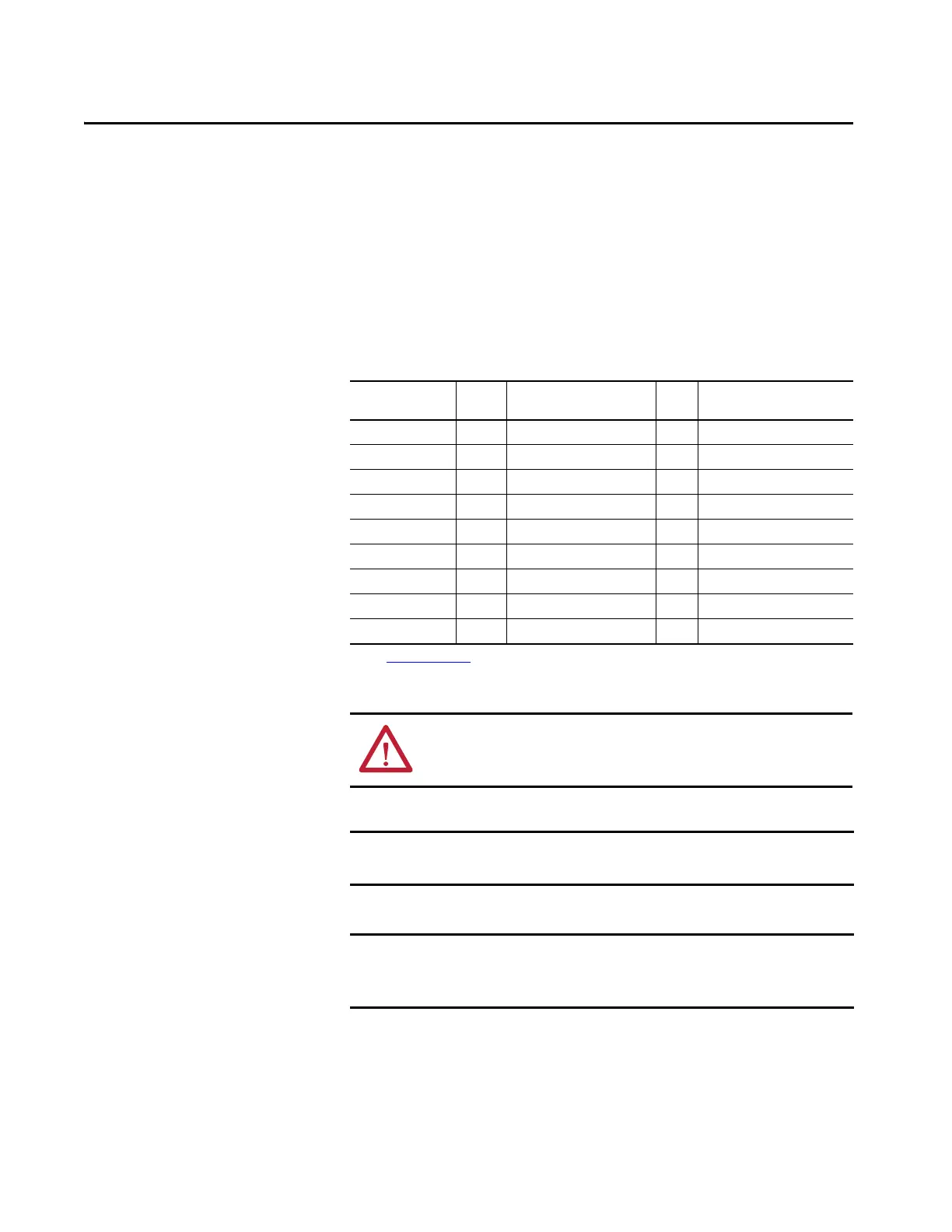
Table 9 - Fiber-optic Adapter Board-to-ASIC Circuit Board Connections
Fiber-optic
Adapter Connector
Type Signal Description:
Reference to ASIC Board
Type ASIC Board Fiber Connector
(1)
(1) See Figure 35 on page 115 for ASIC board fiber-optic connectors.
H1 TX Gate_Enable RX H1
H2 TX U_Gate RX H2
H3 TX V_Gate RX H3
H4 TX W_Gate RX H4
H5 TX A/D Convert RX H5
H6 TX VBUS_RX RX H6
H7 RX VBUS_TX TX H7
X2 From 24V DC Power To X10
X3 From Auxiliary 24V DC power supply To T10 power supply connector
ATTENTION: Hazard of permanent eye damage exists when using optical
transmission equipment. This product emits intense light and invisible
radiation. Do not look into fiber-optic ports or fiber-optic cable connectors.
IMPORTANT When mishandled, the ability of fiber-optic cables to transmit data is
greatly diminished.
IMPORTANT The minimum inside bend radius for fiber-optic cable is 25.4 mm (1 in.). Any
bends with a shorter inside radius can permanently damage the fiber-optic
cable. Signal attenuation increases with decreased inside bend radii.
 Loading...


