96 Rockwell Automation Publication 20Y-TG001C-EN-P - April 2017
Appendix B Schematic Diagrams
System Schematics for Frame
10 in IP20 2500 MCC Style
Enclosure
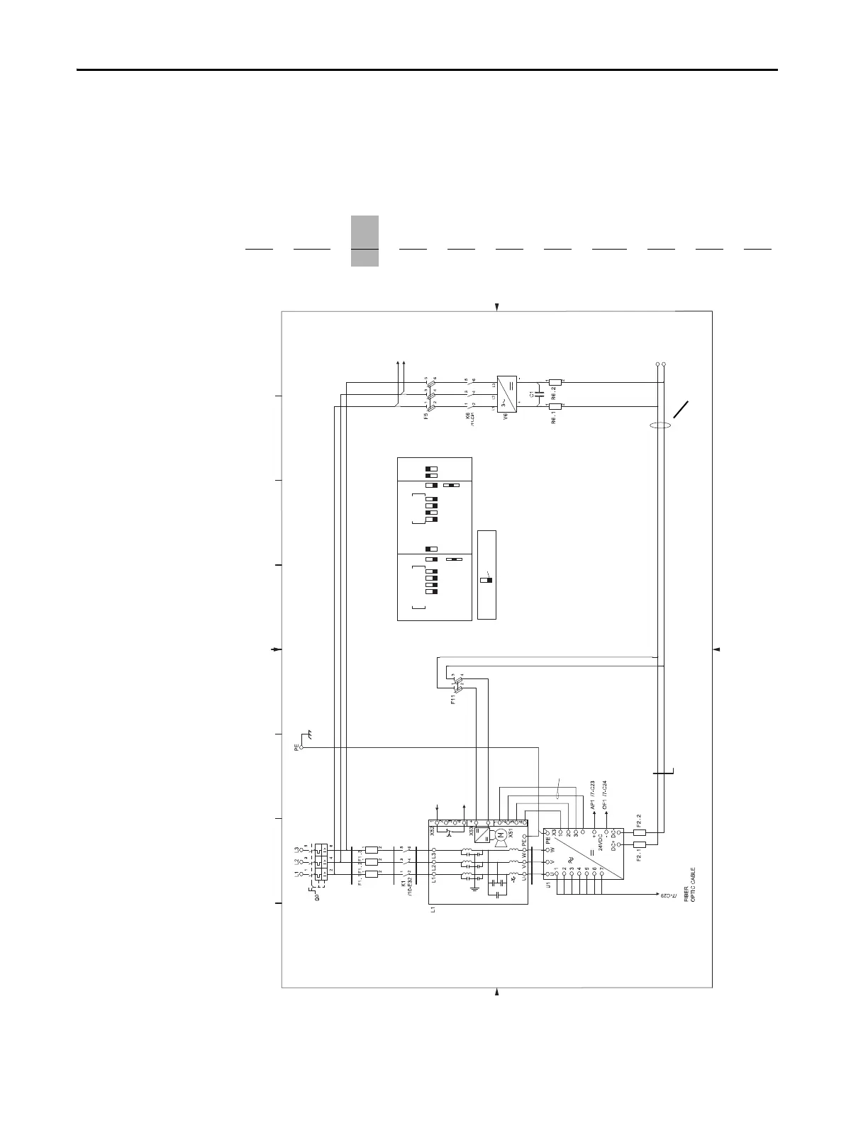
The following system schematics are for the AFE Frame 10 in an IP20 2500
MCC Style enclosure. The PowerFlex® AFE catalog number has an enclosure
code of P for standard color (or W for optional gray color) as shown in this
example catalog string. For other enclosure designs, contact the supplier of the
system for the system schematics.
Position
1…3 4 5…7
8 9 10111213 141516
20Y D 460
P0ANNA NA0
a bc
def ghi j kl
6181
6182
6180
7070
CABLE
MAIN CIRCUIT
CABLE
BUS BAR
61316130 6132
6050
6051
6052
6172 6173 6174
6200 6201 6202
6241 6242
L1 /8-A2
L2 /8-A2
/7-G7 TF+1
TF11 /7-G15
X70 Wire
Connected to -DC secondary side of
fan inverter fuses in power structure
(CAUTION: High Voltage -DC bus potential)
CABLE
62516250 6252
BUS BAR
DC+
DC–
DC+
DC–
TRIP SETTING
Switch handle
Switch Key:
In = * I2 =
I3 =
Inx
Factory default settings are based
on 40 ˚C ambient temperature.
*In = 600A for 400/480V.
*In = 400A for 600/690V.
0.4
+
0.04
0.08
0.16
0.32
1
ON
100
OFF
50
%
1.5
2
5.5
0
0
0
0
3s
t1
S
I
12s
I = 6I1
0.1s
0.25s
I = 8In
L IN
0
0
t1
0
0
Inx∑
ABC DE FGH
01
02
03
04
05
06
07
08
09
10
11
12
13
14
15
16
17
18
19
20
21
22
23
24
25
26
27
28
29
30
31
32
33
34
35
36
37
38
39
40
41
42
01
02
03
04
05
06
07
08
09
10
11
12
13
14
15
16
17
18
19
20
21
22
23
24
25
26
27
28
29
30
31
32
33
34
35
36
37
38
39
40
41
42
-DC Bus
Figure 19 - Frame 10 in IP20 2500 MCC Style Enclosure – Sheet 6 (400/480V and 600/690V)
Factory-installed Common Mode Core
 Loading...


