42 Rockwell Automation Publication 20Y-TG001C-EN-P - April 2017
Chapter 4 AFE Power Structure Component Section
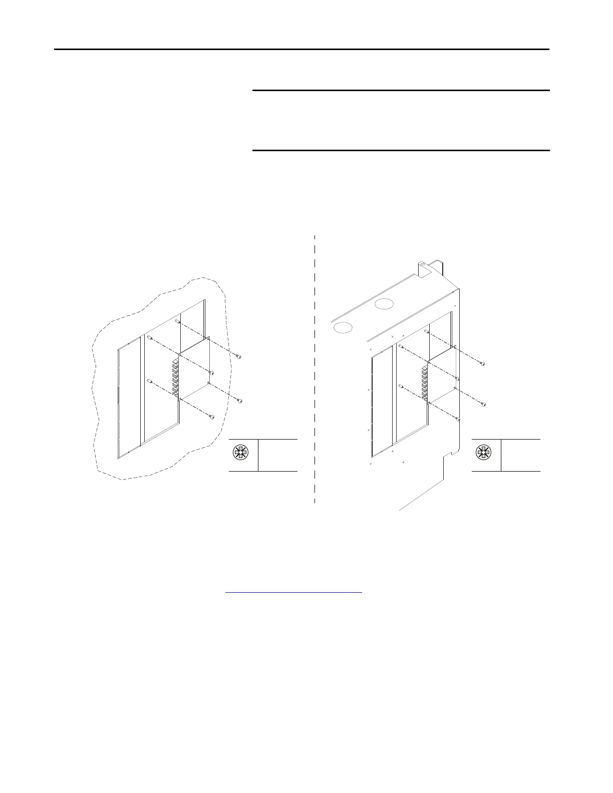
5. Remove the four screws that secure the fiber-optic adapter board to the
stand-offs on the back of the control box (IP20) or control frame
(IP21).
6. Remove the fiber-optic adapter board.
Install the Fiber-optic Adapter Circuit Board
Install the fiber-optic adapter circuit board in reverse order of removal. See
Torque Specifications
on page 36.
IMPORTANT The minimum inside bend radius for fiber-optic cable is 25.4 mm
(1 in.). Any bends with a shorter inside radius can permanently
damage the fiber-optic cable. Signal attenuation increases with
decreased inside bend radii.
PZ2
0.9 N•m
(8 lb•in)
For AFE in IP21 Rittal
Enclosure
For AFE in IP20 2500 MCC
Style Enclosure
PZ2
0.9 N•m
(8 lb•in)
 Loading...


