Rockwell Automation Publication 20Y-TG001C-EN-P - April 2017 41
AFE Power Structure Component Section Chapter 4
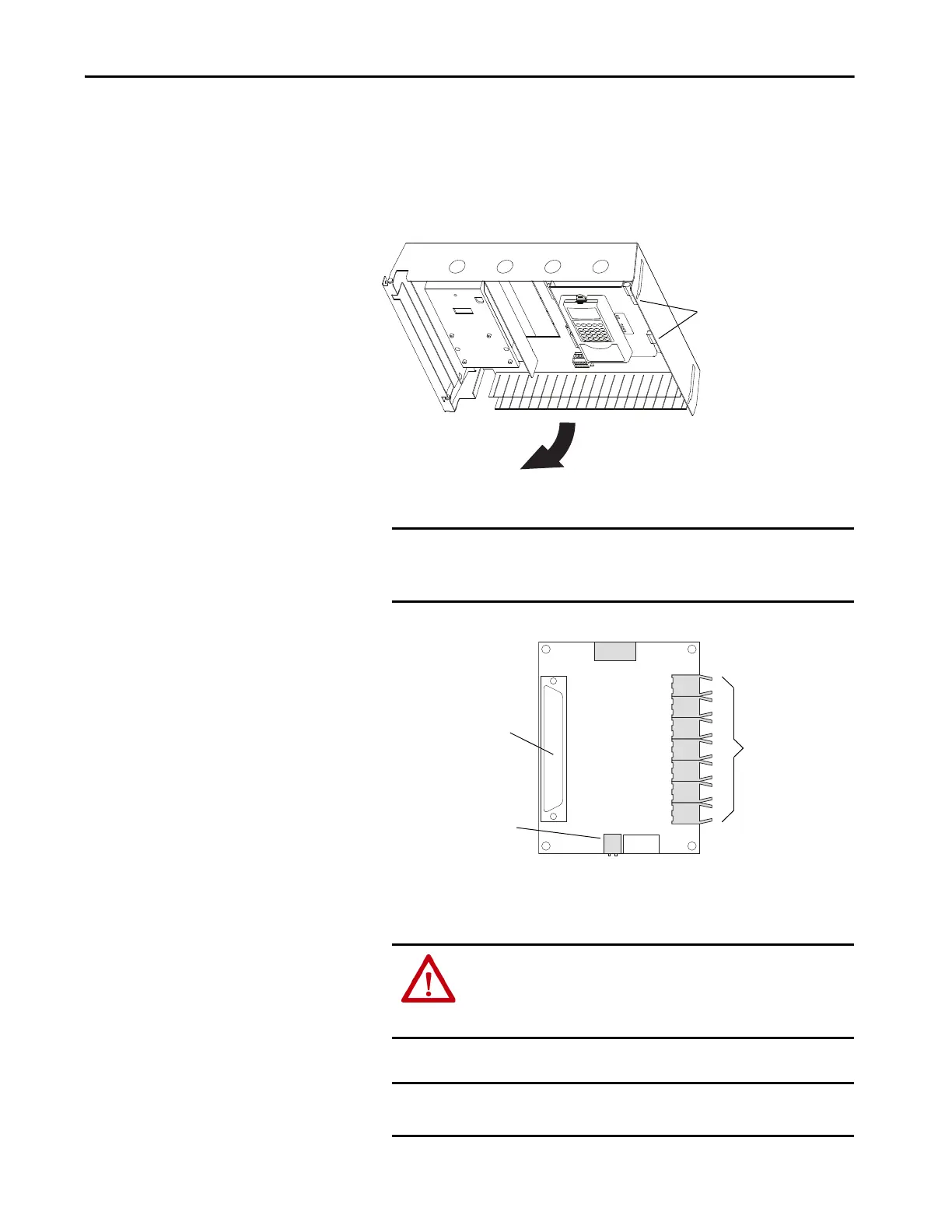
For an AFE in an IP21 Rittal enclosure, do the following:
a. To access the control frame, open the enclosure door.
b. To open the control frame, loosen the T8 screws.
c. Open the control frame, which exposes the back of the control box to
access the fiber-optic adapter board.
3. Disconnect the cables from X2 and X3 of the fiber-optic adapter board.
4. Carefully disconnect the fiber-optic cables from the right side of the
circuit board, and carefully set them aside.
IMPORTANT Note polarity when removing X2 and X3 wires. If polarity is not
maintained when reinstalling these wires, the ASIC board or fiber-
optic board can be damaged.
ATTENTION: Hazard of permanent eye damage exists when using
optical transmission equipment. This product emits intense light
and invisible radiation. Do not look into fiber-optic ports or fiber-
optic cable connectors.
IMPORTANT When mishandled, the ability of fiber-optic cables to transmit data
is greatly diminished.
Loosen T8
Torx-head
Screws
Sockets for
Fiber-optic
Cables
X1 disconnects from the
control board when you
remove the board from the
control frame.
Connects to 24V
DC Power
 Loading...


