116 Rockwell Automation Publication 20Y-TG001C-EN-P - April 2017
Appendix C Connector Descriptions
Hardware Connections
This section describes the hardware connections.
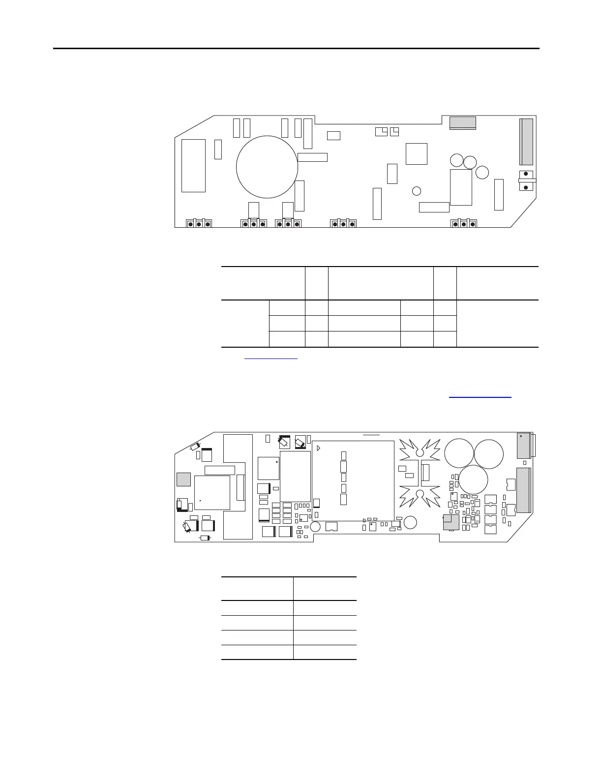
Figure 36 - AFE Power Structure Fan Inverter Circuit Board Connectors
Table 11 - ASIC Board - AFE Power Structure Fan Inverter Board Connections
For part number information, see the PowerFlex 700H, 700S, and 700AFE
Drive Fan Systems Installation Instructions, publication PFLEX-IN029
.
Figure 37 - LCL Filter Fan Inverter Circuit Board Connectors
Table 12 - LCL Filter Fan Inverter Circuit Board Connections
ASIC Board Connector
(1)
(1) See Figure 35 on page 115 for ASIC board connectors.
Pin Signal Description Pin AFE Power Structure Fan
Inverter Board
Connector
X11 From 2 ASIC_+15V To 2 X8
From 3 FAN_CONTROL To 3
To 4 FAN_ALARM From 7
LCL Filter DC Fan
Inverter Board
LCL Filter DC Fan
Assembly
X1 X1
X3 X3
X8 X51
X4 X53
 Loading...


