Rockwell Automation Publication 20Y-TG001C-EN-P - April 2017 25
Active Front End System Overview Chapter 2
AFE in IP00 Open Chassis
Configuration
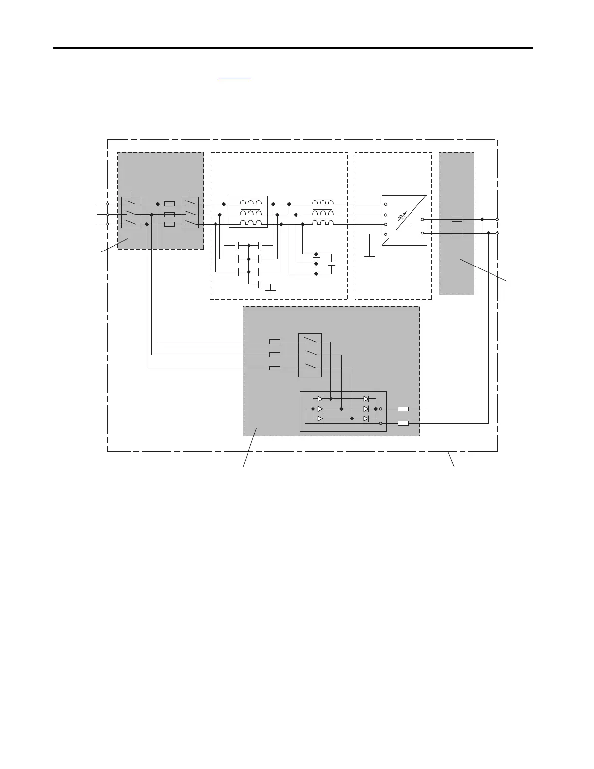
Figure 7 shows a basic one-line diagram for an AFE system in an IP00,
NEMA/UL open chassis configuration, and the parts the customer must
supply.
Figure 7 - Basic One-line Diagram for AFE in IP00 Open Chassis Configuration
Customer-
supplied
Parts
Customer-
supplied
Parts
Customer-supplied Parts
Customer-supplied enclosure
DC Bus
Output
L1
3 Phase
AC Input
L2
L3
PowerFlex
Active Front End System
Precharge
Circuit
R6.1
R6.2
+
-
LCL Filter (L1) AFE
Power Structure (U1)
DC
Fuses
U2
V2
W2
C1
C2
C3
C4
C5
C6
U1
U1
V1
W1
U
DC+
DC-
V
F2.1
F2.2
W
PE
PE
Input
Contactor
K1
Fuses
F1.1-F1.3
Input
Breaker
Q0
AC Line Switchgear
Precharge
Contactor
Precharge
Fuses
F5
K6
 Loading...


