Rockwell Automation Publication 20Y-TG001C-EN-P - April 2017 55
AFE Power Structure Component Section Chapter 4
Install the Power Structure in the Enclosure
Install the power structure in reverse order of removal. See the PowerFlex
Active Front End User Manual, publication 20Y-UM001
, for fastener torques
of AC supply, DC bus input, and ground connection terminations.
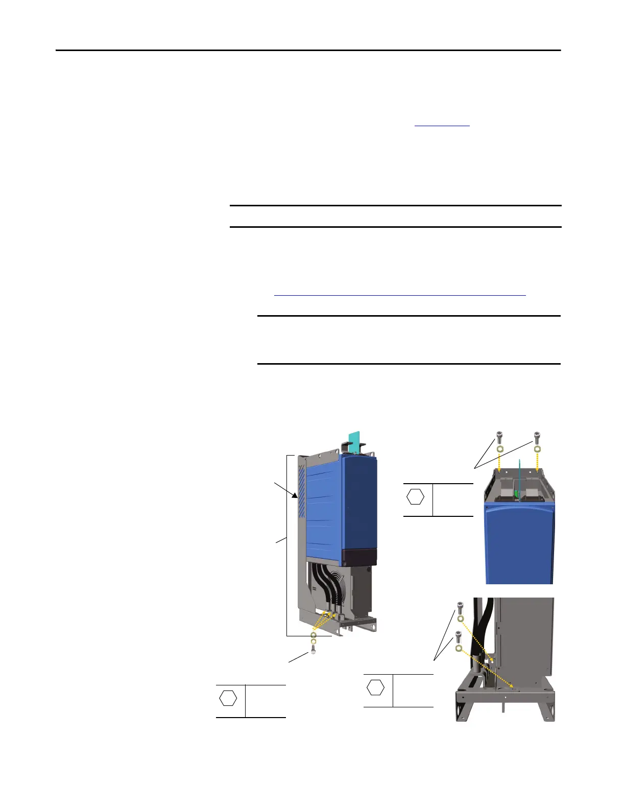
Remove the Power Module from the Power Structure
To remove the power module from the power structure, follow these steps.
1. Remove the power structure from the AFE enclosure.
See Remove the Power Structure from the Enclosure
on page 52.
2. Place the power structure on a flat surface for stability.
3. To facilitate power structure removal from its mounting chassis, place
the power structure on its backside
IMPORTANT Do not attempt to disassemble the power module.
IMPORTANT To access the internal components of the power structure (power
module, DC bus capacitors, balancing resistors, and so forth),
remove the power structure from its mounting chassis.
Remove Screws
M8 x 20
20 N•m
(177 lb•in)
Remove Screws
M8 x 20
20 N•m
(177 lb•in)
Output Cable
Fastening Screws
M10 x 20
40 N•m
(354 lb•in)
Power Structure
Mounting Chassis
Backside of Power
Structure
 Loading...


