56 Rockwell Automation Publication 20Y-TG001C-EN-P - April 2017
Chapter 4 AFE Power Structure Component Section
4. To remove the power structure from its mounting chassis, do the
following:
a. Remove the four M8 x 20 hexagonal screws.
b. Remove the three M10 x 20 output cable screws.
c. Separate the power structure from its mounting chassis.
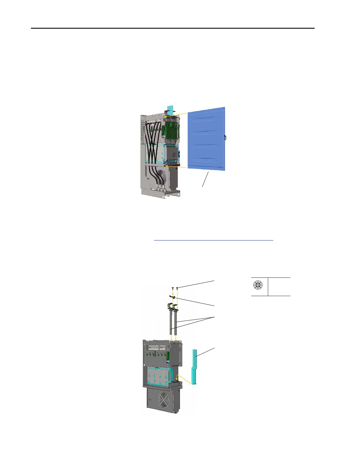
5. To access the internal components, remove the power structure side
panel.
6. Place the power structure on its heatsink side for easy access to the
internal components.
7. Remove the gate driver circuit board.
See Remove the Gate Driver Circuit Board
on page 46.
8. Remove the capacitor leads from the DC input bus bars at the top of the
power structure.
9. Remove the insulator holding plate from between the bus bar terminals.
Remove Screws
Remove Insulator Holding Plate
Remove Bus Bar Terminals
Remove Airflow Channel
PZ2
4 N•m
(35 lb•in)
 Loading...


