114 Rockwell Automation Publication 20Y-TG001C-EN-P - April 2017
Appendix C Connector Descriptions
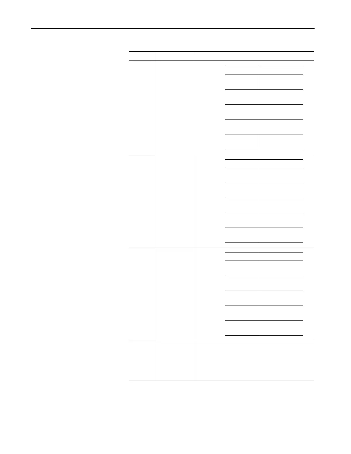
Table 10 - ASIC Board-to-Gate Driver Board Connections
(1)
DTR = N Desat
(2)
ETR = Phase I
2
T
(3)
ITR = Phase overcurrent
ASIC Board Gate Driver Board Signal Description
X3 X13 ‘U’ phase
X4 X14 ‘V’ phase
X5 X15 ‘W’ phase
H13 (WL)
H12 (WH)
H11 (VL)
H10 (VH)
H9 (UL)
H8 (UH)
(WL) H9
(WH) H8
(VL) H7
(VH) H6
(UL) H5
(UH) H4
Fiber-optic gate signals
(connect UH to UH, UL to UL, and so forth)
Ribbon Cable Signal Description
Pin 1
Pin 2
U_Feedback
U_Power_OK
Pin 3
Pin 4
U_DTR
(1)
U_ETR
(2)
Pin 5
Pin 6
U_ITR
(3)
U_DC-
Pin 7
Pin 8
UI
U_DC-_I
Pin 9
Pin 10
U_TEMP
U_DC-T
Ribbon Cable Signal Description
Pin 1
Pin 2
V_Feedback
V_Power_OK
Pin 3
Pin 4
V_DTR
(1)
V_ETR
(2)
Pin 5
Pin 6
V_ITR
(3)
V_DC-
Pin 7
Pin 8
VI
V_DC-_I
Pin 9
Pin 10
V_TEMP
V_DC-T
Ribbon Cable Signal Description
Pin 1
Pin 2
W_Feedback
W_Power_OK
Pin 3
Pin 4
W_DTR
(1)
W_ETR
(2)
Pin 5
Pin 6
W_ITR
(3)
W_DC-
Pin 7
Pin 8
WI
W_DC-_I
Pin 9
Pin 10
W_TEMP
W_DC-T
 Loading...


