EasyManuals Logo

Allen-Bradley PowerFlex AFE User Manual

Allen-Bradley PowerFlex AFE
134 pages
To Next Page IconTo Next Page
To Previous Page IconTo Previous Page
Page #59 background imageLoading...
Page #59 background image
Rockwell Automation Publication 20Y-TG001C-EN-P - April 2017 59
AFE Power Structure Component Section Chapter 4
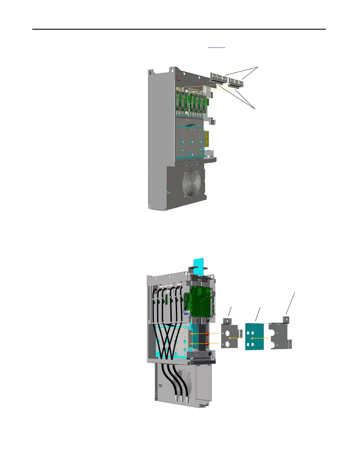
20. Remove the screws (see step 19 picture for screw locations) that secure
the balancing resistor assemblies to the power structure.
21. Remove the balancing resistor assemblies.
22. Remove the M6 x 12 screws that secure the connective DC bus bars and
insulators to the power structure.
Remove Screws
Balancing Resistor
Assembly
DC- Bus Bar
DC+ Bus Bar
Insulator

Table of Contents

Questions and Answers:

Question and Answer IconNeed help?

Do you have a question about the Allen-Bradley PowerFlex AFE and is the answer not in the manual?

Allen-Bradley PowerFlex AFE Specifications

General IconGeneral
BrandAllen-Bradley
ModelPowerFlex AFE
CategoryController
LanguageEnglish

Related product manuals