58 Rockwell Automation Publication 20Y-TG001C-EN-P - April 2017
Chapter 4 AFE Power Structure Component Section
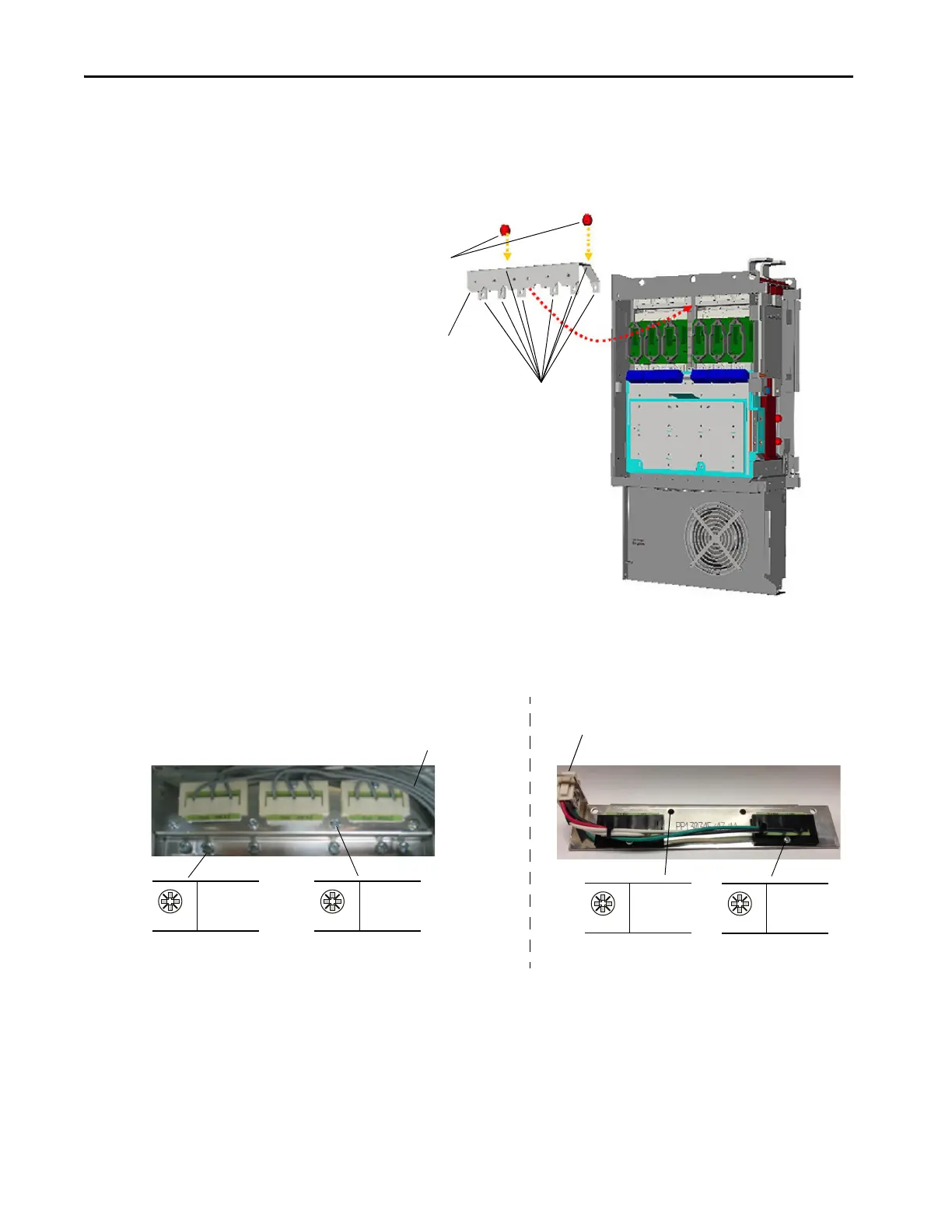
16. Remove the screws that secure the snubber capacitors to the power
structure, and remove the snubber capacitors.
17. Remove the screws that secure the power bus bar and support insulators
to the power structure.
18. Remove the power bus bar and insulators.
Tightening torque for reassembly is 14 N•m (124 lb•in).
19. Disconnect the balancing resistor assembly wires from the DC bus bars.
Remove Screws
Support
Insulators
Power Bus
Bar
P2
4 N•m
(35 lb•in)
PZ2
3 N•m
(27 lb•in)
Assembly Mounting Screws
Older Style Balancing Resistor
Assembly
Newer Style Balancing Resistor
Assembly
P2
4 N•m
(35 lb•in)
PZ2
3 N•m
(27 lb•in)
Assembly Mounting Screws
Remove Wire
Connections from
DC Bus Bar End
Remove Wire
Connections
 Loading...


