Rockwell Automation Publication 20Y-TG001C-EN-P - April 2017 49
AFE Power Structure Component Section Chapter 4
2. If present, remove the protective barriers.
See Remove AFE Protective Barriers
on page 44.
3. Remove the airflow plate.
See Remove the AFE Airflow Plate
on page 45.
4. Remove the protective front cover and terminal cover from the power
structure.
See Remove Protective Covers from the Power Structure
on page 46.
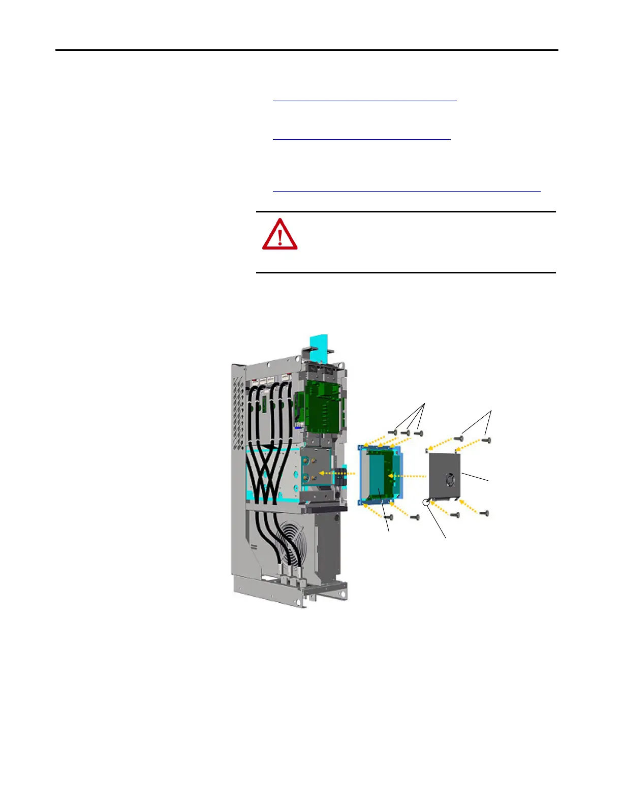
5. Remove the four screws that secure the ASIC cover to the ASIC
assembly, remove the -DC bus connection from the ASIC cover, and
remove the ASIC cover.
6. Unplug the fan, which mounts on the cover, from connector X11 of the
ASIC circuit board.
7. Carefully unplug the fiber-optic cables H1 through H7 from sockets on
the ASIC board, and carefully set them aside.
ATTENTION: The sheet metal cover and mounting screws on the
ASIC circuit board that is on the power structure are energized at (-)
DC bus potential high voltage. Risk of electrical shock, injury, or
death exists if someone comes into contact with the assembly.
Remove Screws and
Cover
Remove -DC Bus
Connection
ASIC Cover
Remove
Screws
ASIC
Assembly
 Loading...


