32 Rockwell Automation Publication 20Y-TG001C-EN-P - April 2017
Chapter 3 Component Test Procedures
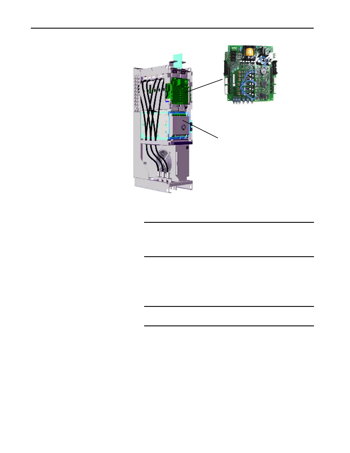
5. Verify that the fiber-optic cables are properly connected between the
gate driver board and the ASIC board.
6. Verify that the fiber-optic cables are properly connected between the
ASIC board and the fiber-optic adapter circuit board.
7. Disconnect the cables and inspect them for scratches and cracks, and
overall integrity.
8. Reconnect the cables, replacing any damaged cables.
Gate Driver Board
ASIC Board
IMPORTANT The minimum inside bend radius for fiber-optic cable is 25.4 mm
(1 in.). Any bends with a shorter inside radius can permanently
damage the fiber-optic cable. Signal attenuation increases with
decreased inside bend radii.
IMPORTANT When mishandled, the ability of fiber-optic cables to transmit data
is greatly diminished.
 Loading...


