14 Rockwell Automation Publication 1734-UM020B-EN-E - August 2019
Chapter 2 Install the POINT I/O 4 Channel IO-Link Master Module
3. Press firmly to seat the mounting base on the DIN rail. The mounting base
snaps into place. Be sure that the orange DIN rail locking screw is in the
horizontal position and that it has engaged the DIN rail.
Install the Module
The module can be installed before or after base installation. Make sure that the
mounting base is correctly keyed before installing the module into the mounting
base. In addition, make sure the mounting base locking screw is positioned
horizontal referenced to the base.
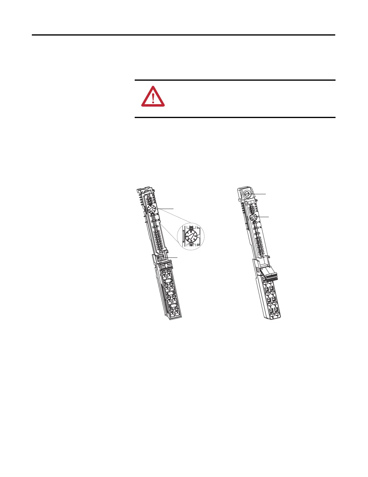
1. Using a bladed screwdriver, rotate the keyswitch on the mounting base
clockwise until the number required for the type of module being installed
aligns with the notch in the base.
2. Make certain the DIN rail locking screw is in the horizontal position. You
cannot insert the module if the locking mechanism is unlocked.
3. Insert the module straight down into the mounting base.
ATTENTION: Do not discard the end cap. Use this end cap to cover
the exposed interconnections on the last mounting base on the DIN
rail. Failure to do so could result in equipment damage or injury from
electric shock.
Turn the keyswitch to
align the number with
the notch. Notch
position 2 is shown.
Be sure the DIN-rail
locking screw is in the
horizontal position.
1734-TB Base
44229
Turn the keyswitch to
align the number with
the notch. Notch
position 2 is shown.
Be sure the DIN-rail locking
screw is in the horizontal
position.
1734-TOP Base
44228

 Loading...


