Rockwell Automation Publication 1734-UM020B-EN-E - August 2019 55
Appendix
A
Connected Data Mapping
About This Appendix
This appendix contains information to help you properly route the data to and
from the IO-Link Master module.
Communicate with the
Module
POINT I/O modules send (produce) and receive (consume) I/O data
(messages). You map this data into the processor’s memory.
The consumed and produced connection sizes may range from 0...32 bytes.
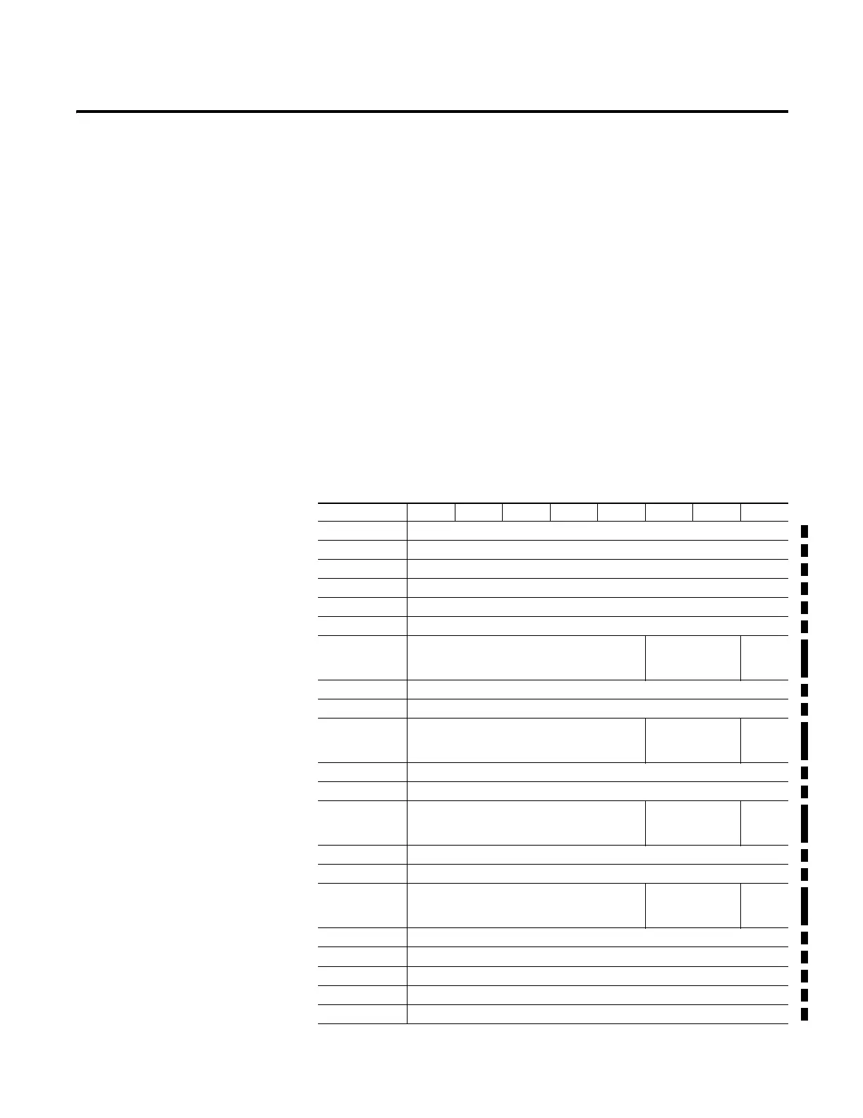
Default Data Map for 1734-4IOL – Configuration Assembly Instance 100
Message size: 46 Bytes
Consumed Byte Bit 7 Bit 6 Bit 5 Bit 4 Bit 3 Bit 2 Bit 1 Bit 0
0 Channel 0 Mode
(1)
1 Channel 1 Mode
2 Channel 2 Mode
3 Channel 3 Mode
4…5 IO-Link Channel 0 Vendor ID
6…8 IO-Link Channel 0 Device ID
9 Reserved Ch0 Data Storage
Backup Levels
Ch0
Send
Config
(5)
10…11 IO-Link Channel 1 Vendor ID
12…14 IO-Link Channel 1 Device ID
15 Reserved Ch1 Data Storage
Backup Levels
Ch1
Send
Config
16…17 IO-Link Channel 2 Vendor ID
18…20 IO-Link Channel 2 Device ID
21 Reserved Ch2 Data Storage
Backup Levels
Ch2
Send
Config
22…23 IO-Link Channel 3 Vendor ID
24…26 IO-Link Channel 3 Device ID
27 Reserved Ch3 Data Storage
Backup Levels
Ch3
Send
Config
28 IO-Link channel 0 Process Output Size
(2)
29 IO-Link channel 0 Process Input Size
30 IO-Link channel 1 Process Output Size
31 IO-Link channel 1 Process Input Size
32 IO-Link channel 2 Process Output Size

 Loading...


