56 Rockwell Automation Publication 1734-UM020B-EN-E - August 2019
Appendix A Connected Data Mapping
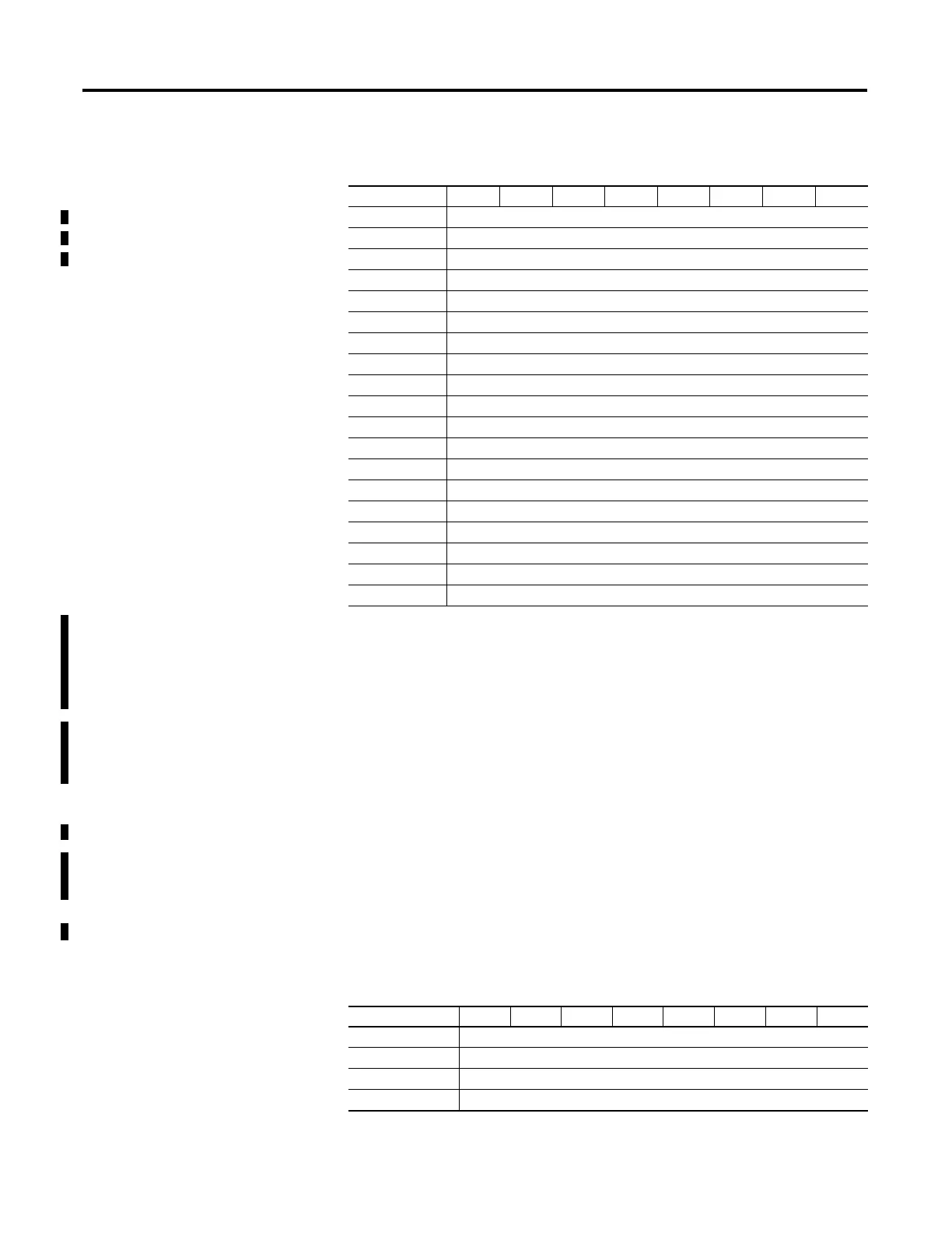
33 IO-Link channel 2 Process Input Size
34 IO-Link channel 3 Process Output Size
35 IO-Link channel 3 Process Input Size
36 Channel 0 Fault Mode
(3)
37 Channel 0 Idle Mode
(1)
38 Channel 1 Fault Mode
(1)
39 Channel 1 Idle Mode
(1)
40 Channel 2 Fault Mode
(1)
41 Channel 2 Idle Mode
(1)
42 Channel 3 Fault Mode
(1)
43 Channel 3 Idle Mode
(1)
44 Channel 0 Input Off to On Time Delay
(4)
45 Channel 0 Input On to Off Time Delay
(2)
46 Channel 1 Input Off to On Time Delay
(2)
47 Channel 1 Input On to Off Time Delay
(2)
48 Channel 2 Input Off to On Time Delay
(2)
49 Channel 2 Input On to Off Time Delay
(2)
50 Channel 3 Input Off to On Time Delay
(2)
51 Channel 3 Input On to Off Time Delay
(2)
(1)
The channel mode selects the type of I/O for the channel. Valid values are:
0: Disabled
1: Standard Output (DO)
2: Standard Input (DI)
3: IO-Link
4: Fallback
(2)
Process Output and Process Input sizes can be in the range of 0 to 32. This value is only valid when the channel
is configured for IO-Link. In standard digital input and fallback modes 1 byte is produced and 0 are consumed, in
standard digital output mode 0 bytes are produced and 1 byte is consumed. When the channel is disabled no
data is produced or consumed.
(3)
Fault and Idle conditions are only valid when the channel is configured for IO-Link or standard digital output.
(4)
Time delays are specified in 1 ms increments, valid range is 0...65 (a value of zero disables the input filter).
(5)
This bit is examined only when the configuration assembly is received while a connection is established (a
connection reconfiguration). If this bit is set the IO-Link device configuration (stored in the associated file
instance) is downloaded to the device on this channel, otherwise it is not.
Default Data Map for 1734-4IOL – Consumed Assembly Instance 101
Message size: 0...128 Bytes
Consumed Byte Bit 7 Bit 6 Bit 5 Bit 4 Bit 3 Bit 2 Bit 1 Bit 0
0...a Output data for Channel 0
(1)
a+1...b Output data for Channel 1
(1)
b+1...c Output data for Channel 2
(1)
c+1...d Output data for Channel 3
(1)
Default Data Map for 1734-4IOL – Configuration Assembly Instance 100
Message size: 46 Bytes
Consumed Byte Bit 7 Bit 6 Bit 5 Bit 4 Bit 3 Bit 2 Bit 1 Bit 0

 Loading...


