Rockwell Automation Publication 1734-UM020B-EN-E - August 2019 57
Connected Data Mapping Appendix A
(1)
Consumed sizes can be in the range of 0...32. Output data for each channel always begin on a 32-bit boundary,
and is enforced by software using the data description for the channel.
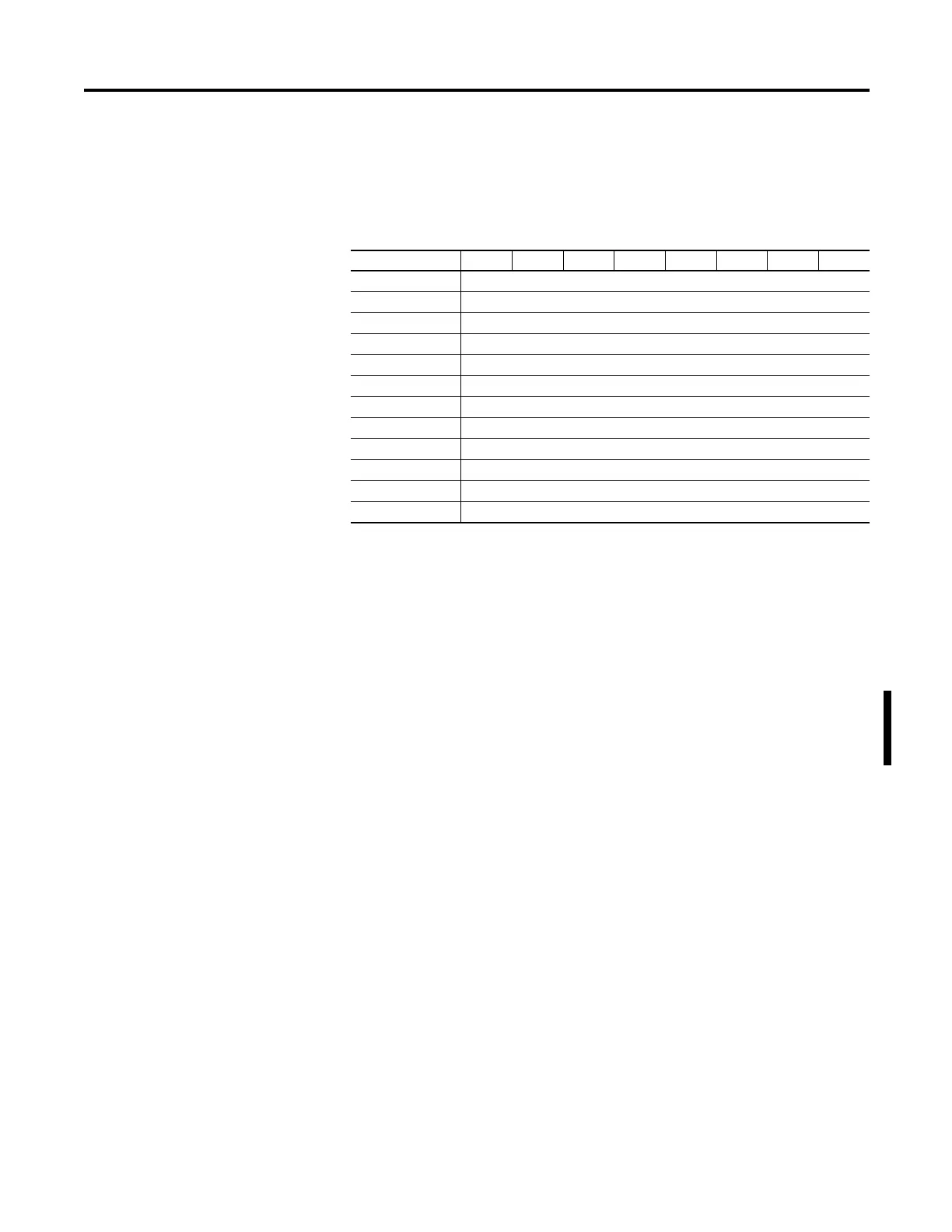
Default Data Map for 1734-4IOL – Produced Assembly Instance 102
Message size: 0...132 Bytes
Consumed Byte Bit 7 Bit 6 Bit 5 Bit 4 Bit 3 Bit 2 Bit 1 Bit 0
0 Channel 0 Status
(1)
2 Channel 1 Status
(1)
4 Channel 2 Status
(1)
6 Channel 3 Status
(1)
8 Channel 0 Most Recent Event
12 Channel 1 Most Recent Event
16 Channel 2 Most Recent Event
20 Channel 3 Most Recent Event
24...a Input data from Channel 0
(2)
a+1...b Input data from Channel 1
(2)
b+1...c Input data from Channel 2
(2)
c+1...d Input data from Channel 3
(2)
(1)
Channel status:
Bit 0: 0 = Roll Up Status, an OR of bits 1 through 7
Bit 1: 0 = Connection to device, 1 = No Connection to device
Bit 2: 1 = Configuration to device in progress
Bit 3: 1 = Device configuration failed
Bit 4: 1 = IO-Link Key failure
Bit 5: 1 = DO Short Circuit
Bit 6: 1 = Process Data Invalid
Bit 7: 1 = Low Power Fault
Bit 8: 1 = IO-Link output value is forced to limit
Bit 9: 1 = No IO-Link size configured
Bit 10: 0 = Channel configured as Fallback is in the IO-Link operating state, or channel not configured for
Fallback; 1 = Channel configured as Fallback is in the DI operating state (This bit is not included in the
roll-up status).
Bits 11…15: Reserved
(2)
Produced sizes can be in the range of 0...32. Input data for each channel always begin on a 32-bit boundary, and
is enforced by software using the data description for the channel.

 Loading...


