EasyManuals Logo

Allied Telesis x530L Series User Manual

Allied Telesis x530L Series
228 pages
To Next Page IconTo Next Page
To Previous Page IconTo Previous Page
Page #111 background imageLoading...
Page #111 background image
x530L Series Installation Guide for Virtual Chassis Stacking
111
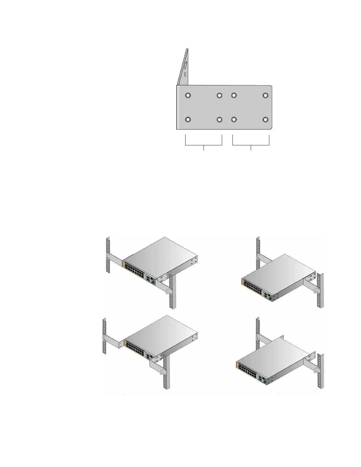
Figure 50. RKMT-J14 Bracket Holes
You can use the different sets of holes on the switch and brackets to install
the switch in the equipment rack in a variety of orientations. You can install
it with the front panel flush with, extending in front of, or recessed behind
the front of the equipment rack. The illustrations in Figure 51 show the
switch orientations with the front panel facing the front of the equipment
rack.
Figure 51. Switch Orientations with the Front Panel Facing the Front of the
Equipment Rack
Set 1 Set 2

Table of Contents

Questions and Answers:

Question and Answer IconNeed help?

Do you have a question about the Allied Telesis x530L Series and is the answer not in the manual?

Allied Telesis x530L Series Specifications

General IconGeneral
BrandAllied Telesis
Modelx530L Series
CategorySwitch
LanguageEnglish

Related product manuals