x530L Series Installation Guide for Virtual Chassis Stacking
117
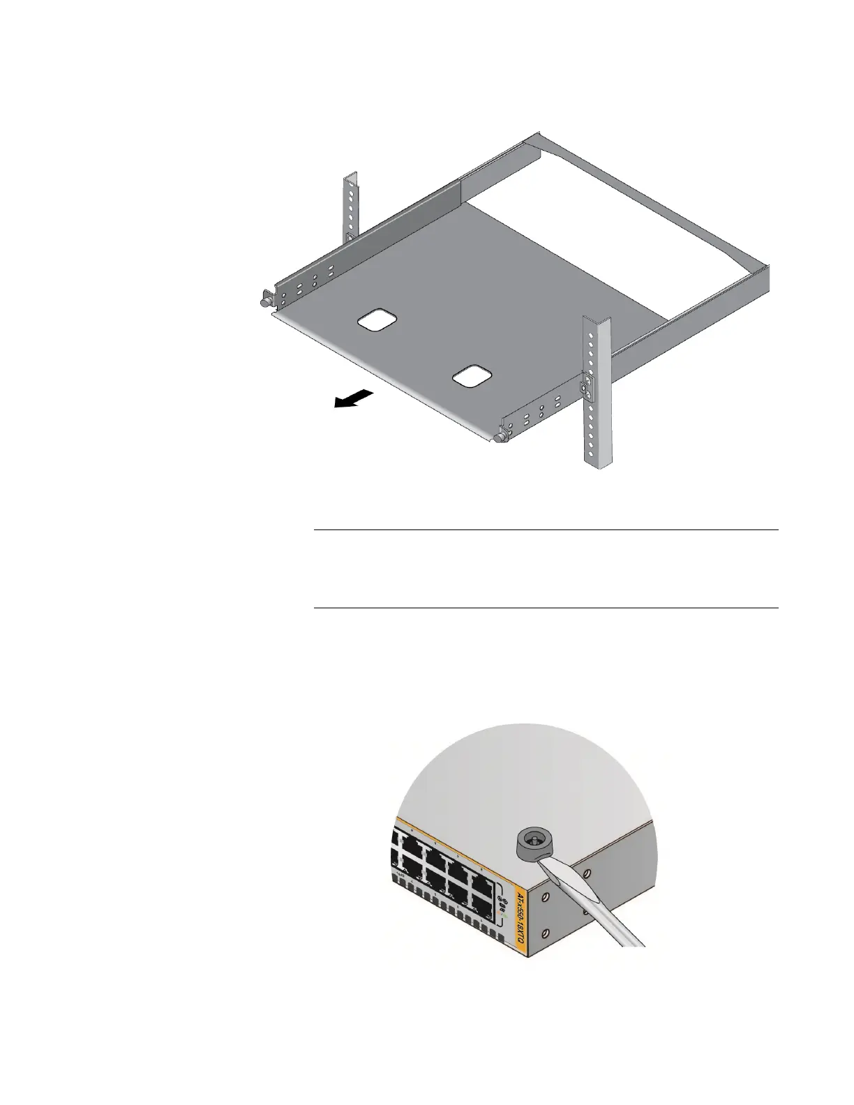
3. Slide out the bracket tray. Refer to Figure 58.
Figure 58. Sliding Out the Bracket of the RKMT-J15
Follow steps 4 to 6 to remove the plastic feet from the bottom of the
switch. If the plastic feet have been installed, you must remove them
to install the switch in the RKMT-J15 Bracket.
4. Place the switch upside-down on a table.
5. Use a small flat-head screwdriver to pry the four plastic feet from the
bottom of the switch. Refer to Figure 59.
Figure 59. Removing the Plastic Feet from the Bottom Panel of the Switch

 Loading...