Chapter 5: Installing the Switch in an Equipment Rack
118
6. Turn the switch over so that it is right-side up.
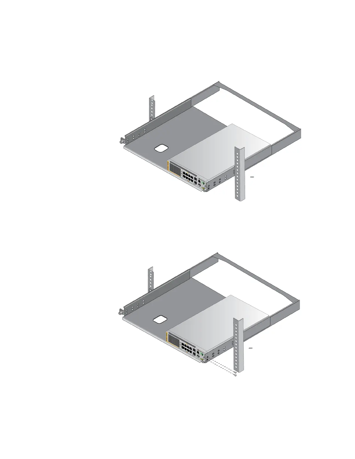
7. Place the switch on one side of the bracket. Align the front panel with
the front edge of the bracket. If you are installing only one switch, you
may install it on either the left or right side. Refer to Figure 60.
Figure 60. Placing the x530L-10GHXm Switch in the RKMT-J15 Bracket
8. Install two M4x6mm screws included with the RKMT-J15 using the first
set of holes to secure the switch to the bracket. Refer to Figure 61.
Figure 61. Securing the x530L-10GHXm Switch to the RKMT-J15 Bracket
9. To install a second switch in the bracket, repeat steps 4 to 8.

 Loading...