x530L Series Installation Guide for Virtual Chassis Stacking
123
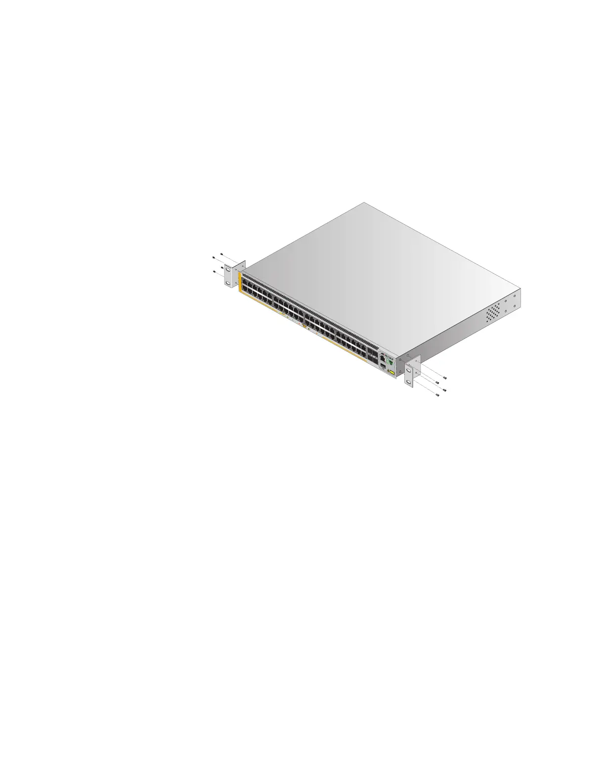
To install the switch in a 19-inch equipment rack, perform the following
procedure:
1. Place the switch on a level, secure surface.
2. Attach the two brackets to the sides of the switch in the selected
position, using the eight M4x6mm screws supplied with the unit. The
illustration in Figure 66 shows the installation of the brackets such that
the front panel of the switch is even with the front of the equipment
rack.
Figure 66. Example of Attaching the Brackets to the Switch
4570
51/S1
52/S2
49
SFP+
50
35
1
7
911
13 15 17 19
21
23
4
68
10 122
16 18 20
14
22
24
27 2925 31
33
35
37
39 41
43
45
47
28
30
32 34
36
26 40 42 44
38
46
48
10G/
1G
1G LINK
ACT
100
LINK
ACT
PD ON
PD ERR
MAX CURRENT
AT-x530L-52GPX
CONSOLE
CL
AS
S
1
LESE
R
PRODUCT

 Loading...


