x530L Series Installation Guide for Virtual Chassis Stacking
135
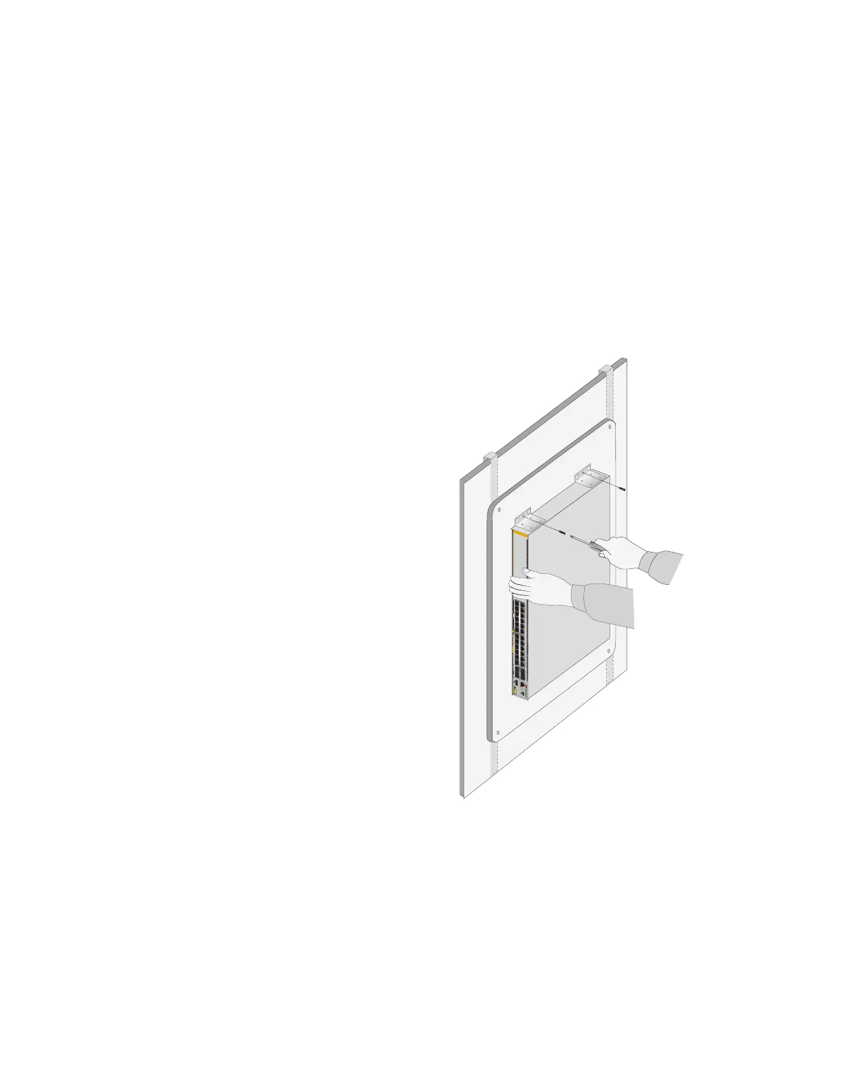
3. After attaching the brackets, have another person hold the switch on
the plywood base on the wall while you secure it with the M4x32.3mm
screws included with the switch. Refer to Figure 76 for the x530L-
28GPX, x530L-28GTX, x530L-52GPX, or x530L-52GTX switch or
Figure 77 on page 136 for the x530L-10GHXm switch.
Follow these guidelines as you position the switch on the wall:
Position the switch so that the front panel is facing up, left or right.
Refer to Figure 76. Do not install it with the front panel facing down.
Provide sufficient space from other devices or walls so that you can
access the front and back panels, and for adequate air flow for
ventilation.
Figure 76. Securing the x530L-28GPX, x530L-28GTX, x530L-52GPX, or
x530L-52GTX or x530L-52GTX Switch to the Plywood Base
35179111315171921 23 27/S1
28/S2
25 SFP+
26
AT-x530L-28GTX
16 18 2014
10G/1G
46810122 22 24
FDX HDX COL
1G LINK ACT 100 LINK ACT 5G/2.5G/1G LINK ACT 100 LINK ACT
PORTS 21-24
PORTS 1-20
5G/2.5G/1G/100
CLASS1
LASER PRODUCT
CONSOLE
4595

 Loading...