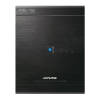
Installation and Connections
Mounting
the
Base
Unit
(PXA-HSOO)
Preparation
1 Check accessory parts.
G)
Power cable
@
USB
cable
(5
m)
® Bracket
® Microphone
(1
set)
® Ai-NET extension cable (5.5 m)
@ Speaker-
RCA
Conversion cable
(20
em)
(Red/White x3
se
ts)
<Microphone>
<Clip> <Adhesive
tape
> ,
~--------
--
-------------------------------------
~
0
®
Screw (M3 x 6
mm)
®
Self-tapping screw (M4 x
14
mm)
~
~
(x4)
(x4)
Velcro fastener
*'
@i
CD-ROM*'· *
3
@)
(x
2)
*
1
Use
when
ne
ce
ssa
ry
*
2
For details
on
how
to
install
and
u
se
the CD-
ROM
, "Sound
Manager
for
PXA
-H
800
,"
ref
er to
th
e Owners
Manual-
PC
guide.
*
3
For details
on
how
to
install
and
use the CD-ROM, "SETUP
DISC,"
refer to the
Owners
Man
u
al
- PC g
uid
e.
Installation example 1
• Set
the
installation location.
• Check
that
the provided cord
is
sufficiently
lo
ng. Install t
he
unit
whe
re
it
is
not
exposed to water.
Do
not
install
the
uni
t or wiring where
it
interferes with driving or
an air bag.
1
Affix
the
bracket®
to
the
device tightly with
the
4
screws
(M3
x 6 mm) (I).
Bracket (x4)
2 Mark
the
installation screw positions
at
the
installation location.
3 Drill (3mm
diameter
max
.) in
the
marked positions.
Lt.
wARNING
When
making
holes,
be
careful
not
to
damage pipes, tanks, electric wires,
etc.
Doing
so could lead
to
an
accident
or
fire.
4 Install
the
device tightly with 4 self-tapping screws
(M4
x
14
mm)
@.
Self-tapping screw (M4 x
14
mm)
(x4)
I
Installation example 2
1 Cut
out
the
external box
paper
template
along
the
perforation.
2 Temporarily hold
the
paper
template
in place
at
the
installation position with adhesive
tape.
3 Put a
bracket®
in
a
predetermined
position
on
the
paper
template
and
mark
where
a screw is
to
be
fixed.
For
details on h
ow
to ins
ta
ll
the
brackets,
r
efe
r to
step
5.
4 Drill a hole (3mm
diameter
max.).
Lt.
wARNING
When
making
holes,
be
careful
not
to
damage pipes, tanks, electric wires,
etc.
Doing
so could lead
to
an
accident
or
fire.
3-E
N