Connecting a Non Ai-NET AV Head Unit, External
Input
and External Amplifier
•
Input
Pattern : 5.1
ch
Input
AUXINPUT
(Front Left) (Front Right)
(Rear
Left)
Ai-NET/RCA Interface
cableKCA-121B
(Sold separately)
AI-NET/RCA Interface
cableKCA-121B
(Sold separately)
Fiber
optic
cable
{Sold separately)
(R
ea
r
Righ
t)
(C
enter)
(Subwoofe
r)
White
White
RCA
extension cable
White
(Sold separately)
White
RCA
extension cable
{Sold separately)
Fiber
optic
cable
To
Digital
Output
:=======::::::;
(s
ld
I
I
Terminal
,---o
__
se-'p'-a_r_a_te_y'-------D
_
___
___
~
Optical
Digital
Compatible
, 6
DVD
Player
,
etc.
@~~
~
.
et
11u
~~\7f
~&o:i
.
@J
~
,~~~
~
o
l
~ ~
~ ~
fd:ttl
~;'LJ
•
,___,J
.-
~
.
'•, @ *
::-~~~',,
',,,
~
--~=·:....___;
~@
~[-='==;
~
~
~:
:.::=:
~
~
~
-:F~
~~:
-
~
*
~
:
:~
~illf
,Audio
output
jacks
1
v
TV Tuner
or
Video
Player, etc.
TV Tuner
or
Video
Player, etc.
'
··
··
<>··
..
Computer
connection
terminal
To External
Amplifier
(see page 10}
White
Red
Red
White
' '
' '
' '
' '
Guide Control Lead
White/Green
Navigation
audio
input
connector
Remote Control
Output
Lead
Blue/White
Ground Lead
Black
Battery Lead
Yellow
Fuse 10A
Illumination
Lead
Orange
Remote
On
Lead
Blue/White
RCA
extension cable (Sold
se
aratel I
RCA
extension cable (Sold separately)
RCA
extension cable (Sold separately)
White,....,.....__u-
Red
RCA
extension cable (Sold separately)
~
-
-
--r
:~
Commandercable
Q-~~~~-~~
:
:f
l
~
l
=
=~-
~
-
:::IJ,I
}
(RUX-CSOO
included)
RUX-CSOO
{Sold separately)
Not
Connected
To
Remote On Lead
of
an
External
Amplifier
f Connect
to
a
metal
part
of
chassis
body
with
a screw.
~~
J~
Ill
urn nat1on L d
ea
~
Orange
Remote On Lead
~
Blue/White
Center Speaker
Output
~
Subwoofer
Output
Rear
Output
*
2
~
/
~
........,_
Front
Output
*
2
~
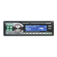
Non AI-
NET
AV Head
Unit
(Sold separately)
*
1
Wh
en using a h
ea
d
unit
that is
not
A
i-N
ET
co
mpatibl
e,
the
RUX
-
CSO
O Co
mma
nder (sold separatel
y)
is req
ui
red.
~CAUTION
When using fiber cable, follow
the
guidelines below:
• When laying
or
bundling optic fiber cables,
the
minimum
bending
radius should
be
30 mm. Bending
beyond
the
radius will
break
the
cable, resulting in
no
digital
sound
being
output.
•
Do
not
put
th
e
product
or o
th
er items
on
the
opti
c fiber ca
ble
.
14-
EN