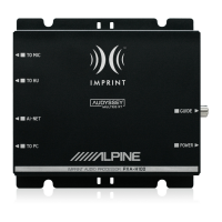
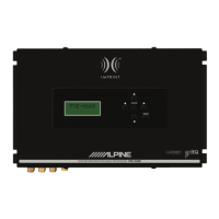
Connecting a Non Ai-NET Head
Unit,
External
Input
and
External
Amplifier
•
Input
Pattern
: 2chx3
Input
CH-1
(L)
I
AUXl
L (Left)
I
CH-2
(R)
R
(R
ight)
AUXINPUT
CH-3 (L)
I
CH-4(R) CH-5
(L)
I
CH-6
(R)
AU
X2
A
UX3
L
(Left)
I
R
(R
ight) L
(Lef
t)
I
R (Right)
Ai-NET/RCA
Interface
cable
KCA-121B
(Sold separately)
White White
RCA
extension cable
White
(Sold
separately)
Ai-NET/RCA Interface
cable KCA-121B
White
White
RCA
extension cable
White
(Sold separately)
~
EP~
_
___;__....:.....__---<~
(Sold
separately)
To
Digital
Output
Fiber
optic
cable
(Sold
separately)*
2
Fiber
optic
cable
Terminal
..---------,
Optical
Digital
Compatible
DVD
Player,
etc.
,..--(S_o_ld_se...;p_a_r_at_e_ly;...l_
*_
2
------D
.. _
__
__
•
Optical
Digital
Compatible
DVD
Player,
etc.
To
Digital
Output
'--------'
Terminal
Audio
output
jacks
To External
Amplifier
TV Tuner
or
Video
Player, etc.
TV Tuner
or
Video
Player, etc.
White
Computer
connection
terminal
(see
page
101
a:.~~a~S§§~
·
~·
~
~
·-
--r
:~
Commander cable
D-~1\.:!:~~-
~~:~
1
~
1
==~
-
dJJ
Guide
Control
Lead
(RUX-C800
included)
} Not
c-n•<tod
RUX-C800 (Sold
separately)
Red
Red
White
White/Green
Navigation
audio
input
connector
1'-R~e_m_o_t-:e-:C_o_n_tr_o_I_O_u_,tp,_u_t_L_e..:..a_d
--Ell~
To
Remote
On
Lead
of
an
Blue/White
External
Amplifier
Ground
Lead
~
~
Connect
to
a
metal
part
of
Black chassis
body
with
a screw.
Battery
Lead
Yellow
Fuse
10A
Illumination
Lead
Orange
Remote
On Lead
Blue/White
~~
~
~
Illumination
Lead
Orange
Remote
On
Lead
Blue/White
RCA
extension cable
White
White
(Sold
separately)
White
White
>---I
TV Tuner
or
Video
Player, etc.
RCA
extension cable
(Sold separately)
>----t
TVTunerorVideo
Player, etc.
Red Red
RCA
extension cable
(Sold
separately)
*
1
Wh
en using a head unit that
is
not
Ai-NET
compatible, the
RUX
-
CBOO
Co
mmand
er
(so
ld separatel
y)
is required.
*
2
Use
when connected with
an
Op
tical Digital compatible U
nit
.
~CAUTION
When using fiber
cable, follow
the
guidelines below:
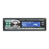
Non Ai-NET Head
Unit
(Sold
separately)
•
When
laying
or
bundling
optic fiber
cables,
the
minimum
bending
radius
should
be
30
mm. Bending beyond
the
radius
will
break
the
cable, resulting
in
no
digital
sound
being
output
.
•
Do
not
put
the
product
or
oth
er
items
on
th
e optic fiber
cable.
15
-E
N