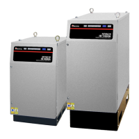
IS-300A
Contents
1
Thank you for purchasing our DC Inverter Welding Power Supply IS-300A.
This operation manual describes its method of operation and precautions for use.
Read this operation manual carefully prior to use. Store appropriately for ready reference.
Contents
1. Special Precautions ........................................................................................................ 1-1
(1) Safety Precautions....................................................................................................... 1-1
(2) Precautions for Handling ............................................................................................. 1-4
(3) On Disposal ................................................................................................................. 1-5
(4) Warning Labels for Safety ........................................................................................... 1-5
2. Features ........................................................................................................................... 2-1
3. Name and Functions of Each Section ........................................................................... 3-1
(1) Front ............................................................................................................................ 3-1
(2) Rear ............................................................................................................................. 3-3
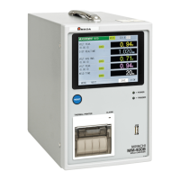
(3) MA-660A (Sold Separately) ......................................................................................... 3-4
4. How to Operate Screens ................................................................................................. 4-1
(1) MENU Screen .............................................................................................................. 4-1
(2) POWER SUPPLY STATE Screen ............................................................................... 4-2
(3) SCHEDULE Screen ..................................................................................................... 4-3
(4) MONITOR Screen ..................................................................................................... 4-13
(5) MONITOR SET Screen ............................................................................................. 4-16
(6) NG SIGNAL SELECT Screen .................................................................................... 4-18
(7) OUTPUT SELECT Screen ......................................................................................... 4-20
(8) COPY SETUP DATA Screen ..................................................................................... 4-21
(9) MODE SELECT Screen ............................................................................................. 4-23
(10) MONITOR MODE Screen ........................................................................................ 4-39
(11) STEPPER COUNT Screen ...................................................................................... 4-45
(12) PRECHECK Screen ................................................................................................ 4-47
(13) I/O CHECK Screen .................................................................................................. 4-48
(14) RESET TO DEFAULT Screen ................................................................................. 4-49
(15) PROGRAM PROTECT MODE Screen .................................................................... 4-50
5. Installation and Connection ........................................................................................... 5-1
(1) Installation Place .......................................................................................................... 5-1
(2) Grounding Work........................................................................................................... 5-2
(3) Basic Connection ......................................................................................................... 5-2
(4) Connection Procedure ................................................................................................. 5-6
(5) Noise Filter................................................................................................................. 5-10
6. Interface ........................................................................................................................... 6-1
(1) Connection Diagram for External Input/Output Signals ............................................... 6-1
(2) Description of External I/O Signals .............................................................................. 6-3
(3) List of External Output Signals .................................................................................... 6-8
(4) Connection of Input Signals ......................................................................................... 6-9
7. Basic Operation ............................................................................................................... 7-1