IS-300A
4. How to Operate Screens
4-32
(m) VALVE MODE
Select the output method (1 VALVE or 2 VALVE) of the solenoid valve signal.
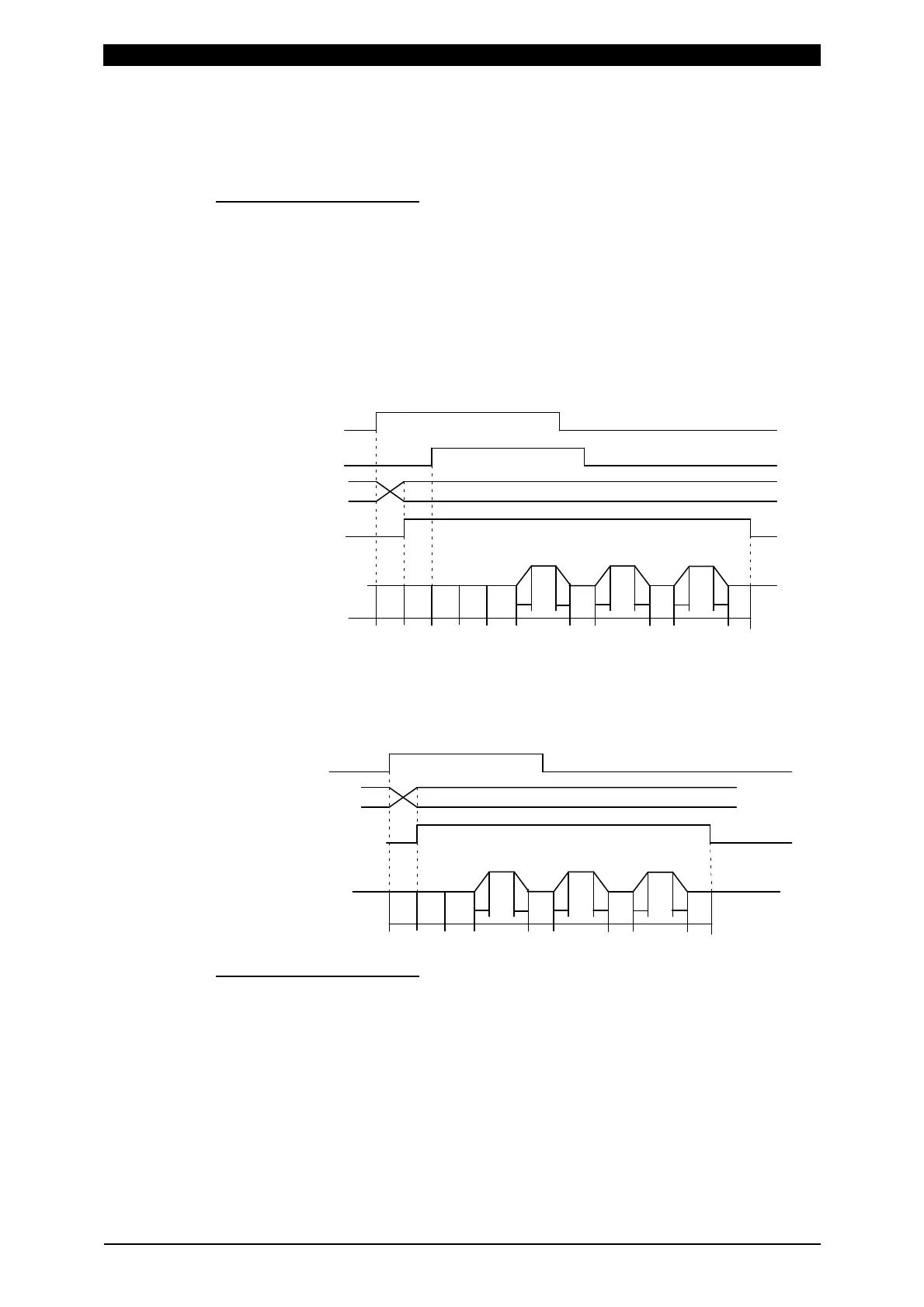
When 1 VALVE is selected
When the 1ST STAGE signal is input, the valve signal (SOL1 or SOL2) with the
selected schedule number is output and the sequence waits for the 2ND
STAGE signal input. Next, when the 2ND STAGE signal is input, the welding
sequence with the selected schedule number starts. After the welding sequence
starts, the valve signal is output until the sequence ends even if the 1ST
STAGE signal is turned OFF.
T: DELAY START SET (1 to 20 ms)
TW: 2ND STAGE signal input wait time (uncertain)
SQD SQZ
UU
D
D
WE1 WE2
U
D
HOCO1
CO2
WE3TW TT
When the 2ND STAGE signal is input, the valve signal (SOL1 or SOL2) with the
selected schedule number is output. After the welding sequence starts, the
valve signal is output until the sequence ends even if the 2ND STAGE is turned
OFF.
SQD SQZ
UU
D
D
WE1 WE2
U
D
HOCO1
CO2
WE3T
When 2 VALVE is selected
2 valve signals (SOL1 and SOL2) are output in a sequence.
When SOL1 is used, the weld force position can be adjusted by the 1ST
STAGE signal input. Adjust the output timing of SOL2 to the start of SQZ.
After the welding sequence starts, the valve signal is output until the sequence
ends even if the 1ST STAGE signal is turned OFF.
When VALVE MODE is set to 2 VALVE, the following functions become
disabled.
・OFF (Repeated operation is not performed.)
・Start mode LATCHED(B), PULSED(B), LATCHED(8), PULSED(8) operation
(E-10 (Schedule setting error) occurs at start up.)
1ST STAGE
2ND STAGE
Schedule selection
(1,2,4,8,16,32,64,128,P)
Valve output
Welding sequence
2ND STAGE
Schedule selection
(1,2,4,8,16,32,64,128,P)
Valve output
Welding sequence
 Loading...


