IS-300A
6. Interface
6-5
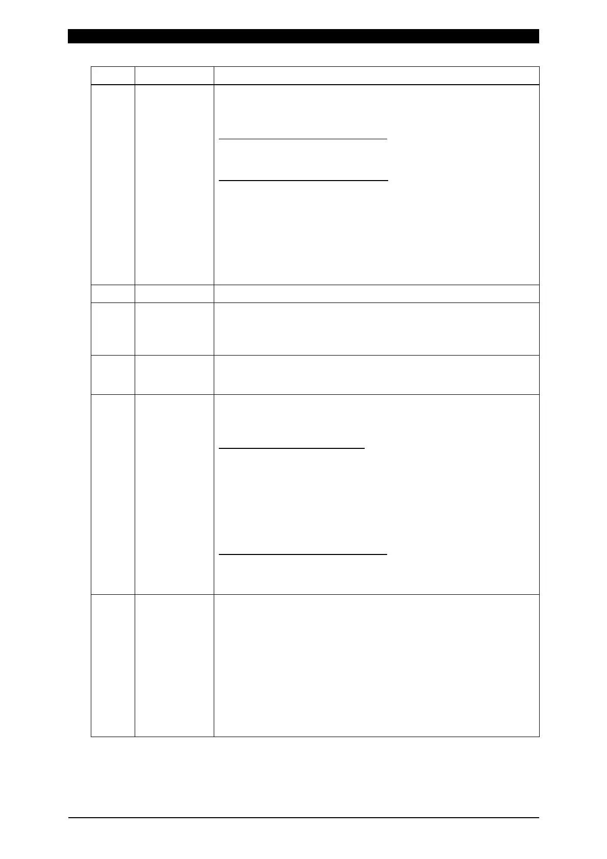
Pin No. Name Description
21
FLOW
SWITCH/
PRG
PROTECT
Flow switch input or Program inhibit input pin.
Switch between functions via the settings on the (9) MODE
SELECT screen described in Chapter 4.
When FLOW SWITCH is selected
Flow switch input pin. Opening this pin will result in a flow rate
error. 20 ms or more is required for receiving the input signal.
When PRG PROTECT is selected
Program inhibit input pin. Closing this pin will not allow you to
change the settings.
When changing the inhibition state with the program inhibit
input pin, press the MENU key to display the MENU screen
after changing the state. Even if the MENU screen is being
displayed, press the MENU key to refresh the MENU screen.
Also, you can set this function on the PROGRAM PROTECT
MODE screen. (See 4. (15).)
22
COM COM pin. This pin is internally connected to the GND chassis.
23
ERROR
RESET
Error/caution reset input pin.
Eliminate the cause of error or caution and close this pin to
reset the error or caution indication.
20 ms or more is required for receiving the input signal.
24
STEP RESET
Step reset input pin. Closing this pin while the STEPPER is ON
will reset the STEP number to 1.
20 ms or more is required for receiving the input signal.
25
WE3 STOP/
COUNT
RESET
WE3 stop input or Count reset input pin.
Switch between functions via the settings on the (9) MODE
SELECT screen described in Chapter 4.
When WE3 STOP is selected
Closing this pin during the WELD3 sequence will switch the
sequence to HOLD.
The welding stop error occurs when the start signal is input
while the WELD3 STOP signal is input.
When this pin is closed before WELD3 welding start after
startup, the current is supplied for at least a control cycle and
WELD3 is stopped to switch the sequence to HOLD.
When COUNT RESET is selected
Closing this pin allows you to reset the counter.
20 ms or more is required for receiving the COUNT RESET
input signal.
26
NG1 (ERROR)
Error signal output pin. This signal is output upon completion of
the welding sequence in the event of an operational error.
If an error occurs, operation will halt until the reset signal is
input.
In NORMAL CLOSE, the pin is closed with the power turned
on, but becomes open with an error occurring.
In NORMAL OPEN, the pin is open with the power turned on,
but becomes closed with an error occurring. (Refer to 4.(6) NG
SIGNAL SELECT Screen.)
The contact is rated at 24
V DC at 20
mA (semiconductor
switch).
 Loading...


