Operating sequence field sprayer
43
AMATRON II-A DB 599 09.01
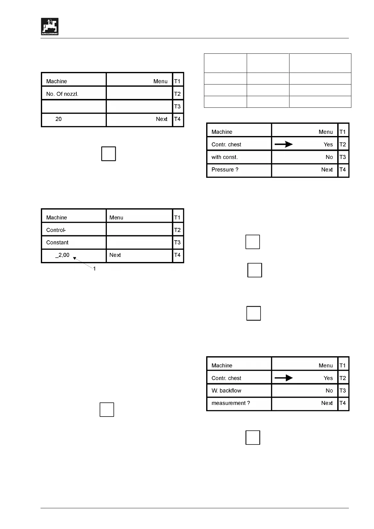
Here you may recheck whether the earlier data for
the part sections have been entered correctly..
Fig. 71
• By pressing key
T4
(Next) you get to the
display in which the control constant is entered
(see para. 7.2.7).
7.2.7 Menu "control constant"
Fig. 72
Enter here the implement specific control constant
(Fig. 72/1) via the ten digit key board. Depending
on the type of field sprayer values between 2 and 5
are possible.
If the control is acting too slow, in-
crease the value.
In case of an overload, i.e. at a re-
quired value of e.g. 200 l/ha the
regulation is from 160 l/ha to 230 l/ha
and again to 180 l/ha etc., the control
constant is too high. Reduce the en-
tered value.
• By pressing key
T4
(Next) the next display
asks for the equipment of the control unit (see
para. 7.2.8).
7.2.8 "Control unit"
The following table shows the equipment of the
different control units:
Table 4: Type of control unit
Control unit With equal
pressure
With return flow
measuring
TG No No
NG Yes Yes
GYesYes
Fig. 73
This display queries the equipment of the control
unit, please observe table 4 – type of control unit.
The arrow indicates the selected type of control
unit.
• Press key
T3
(No) to confirm that it is a con-
trol unit without equal pressure device.
• Press key
T4
(Next) to return to the menu
selection. By pressing this key automatically the
situation is assumed which is marked by the ar-
row position.
• Press key
T2
(yes) to confirm that a control
unit with equal pressure device is connected.
Now the next display inquires whether the con-
trol unit is equipped with a return flow measur-
ing.
Fig. 74
• Press key
T2
(yes) to confirm that the return
flow is guided via the flow meter when one or
several part sections have been switched off. ,
After confirmation the display automatically
jumps into the menu selection.
 Loading...