Construction and function of the field sprayer
BAG0166.5 12.18
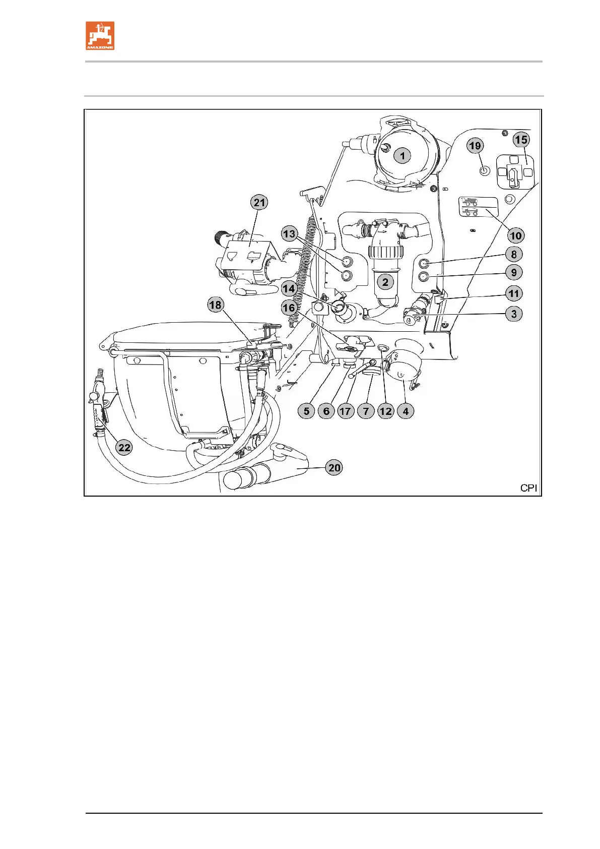
6.2 Overview control terminal
Fig. 65
(2) Pressure filter
(3) Flushing water tank filling connection
(4) Filling connection of the suction chest for
suction hose
(5) Pressure filter outlet
(6) Quick emptying via pump
(7) Suction filter / spray liquid outlet
(8) Work lights
(9) Pump On / Off
(10) Filling level indicator
(11) Display position of the suction chest
(
12) Suction chest button
13) Button to lift / lower the induction bowl
14) ECO – fill rinsing base
15) Function selection switch
16) Additional agitator setting tap / drain residue
17) Suction chest drainage tap
18) Switch tap for ring line / canister flushing
19) Switch on injection button
20) Switch tap Evacuate induction bowl / Ecofill
21) Switch tap - injector
Suction from the induction bowl/Increasing
the suction capacity
22) Spray gun for flushing the induction bowl
 Loading...