2 Display the jog panel as shown in section 10.
3 Use the jog panel to move the crosshead to a suitable position to perform
the compensation: -
If a Tension Compensation is being performed, move the crosshead to fit the
stiff sample into the required grips.
If a Compression Compensation is being performed, carefully move the crosshead
downwards, using the jog panel, until the compression plates are close together,
e.g. separation of approximately 1mm (.04in).
4 Use the jog panel to zero the machine at this position.
5 Close the jog panel.
6 Press on the "Distance Compensation" drop down to display the "Distance
Compensation" names.
7 Select one of the "Empty" names, e.g. “Empty 0”. Note that any previously defined
"Distance Compensation” name may also be selected and replaced if no longer
required.
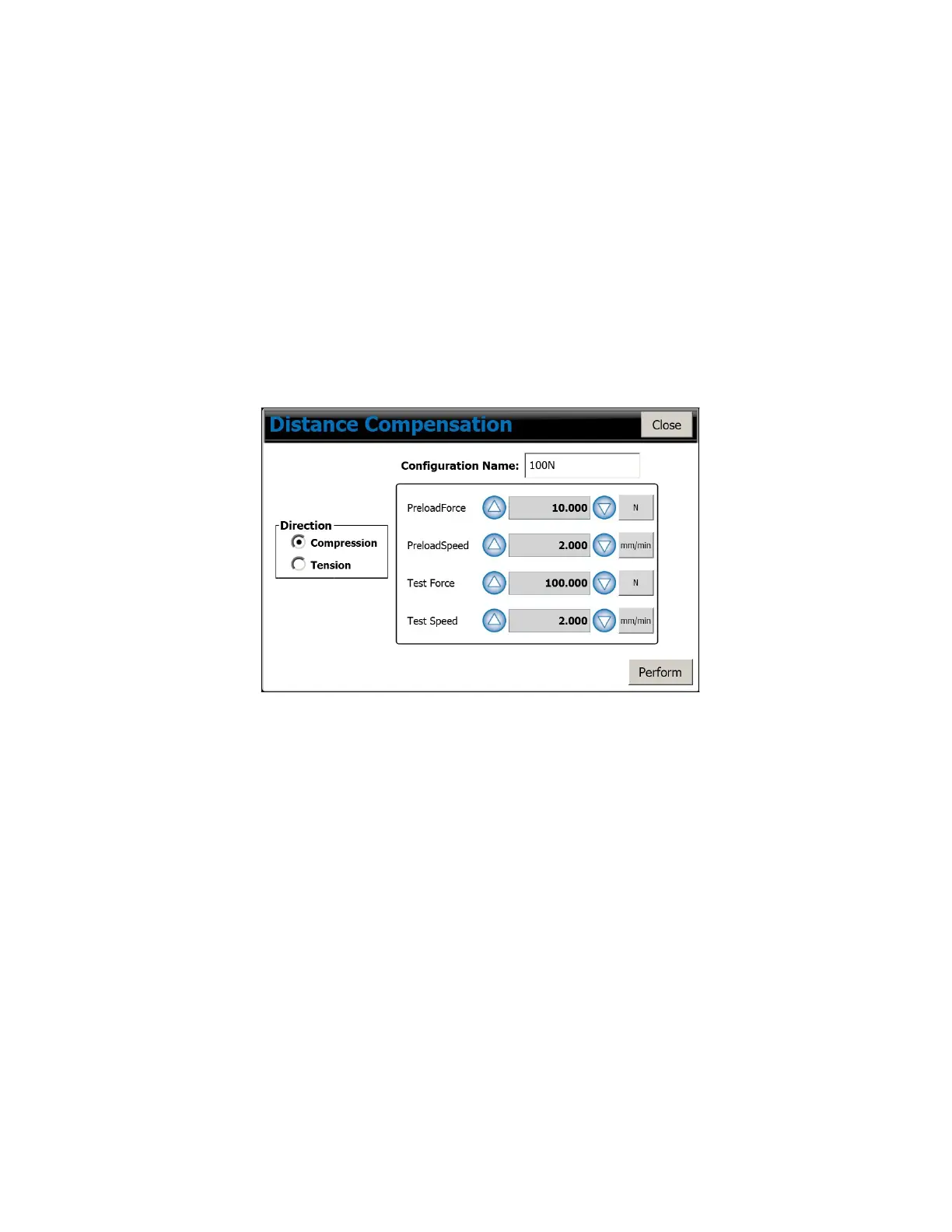
8 Press on the “EDIT” button to display the “DISTANCE COMPENSATION” screen.
9 Select the same direction as the main test direction, e.g. Tension or Compression.
10 Press on “Configuration Name” then enter a suitable name for this compensation
factor, e.g. “100N”.
11 Define a suitable “Test Force”, e.g. the load cell capacity then define a suitable “Test
Speed”, e.g. “5 mm/min”. Care must be taken not to use too high a speed as
load
cell
damage may occur.
12 Define a suitable “Preload Force”, noting that a suitable value is 1% of the “Test
Force” then define a suitable “Test Speed”, which may be the same as the “Test
Speed”, e.g. “5 mm/min”.
CS User Manual
99
 Loading...