User Manual California Instruments
CSW Series 117
5.4.2 AC Function DC Zero Adjustment (ALC can be ON or OFF for the following adjustments)
1. Program the External DMM to the DC function and 10 or 20 VDC range
1
.
2. Program the Low Voltage Range, the AC function, 0.5 volts and 400 Hz
3. Perform the adjustment indicated in Table 6-4 on the Analog Board for the indicated
output phase. Make the adjustment for the lowest DC output signal. Press the OUTPUT
pushbutton to turn on the CSW. With the test station DMM set in DC mode
(autoranging), verify that all output phases are 0 ± 10 mVDC. Adjust pots on the Analog
Waveform Board as required to minimize DC component (Note: R25 [right] controls A,
R85 [middle] controls B and R120 [left] controls C).
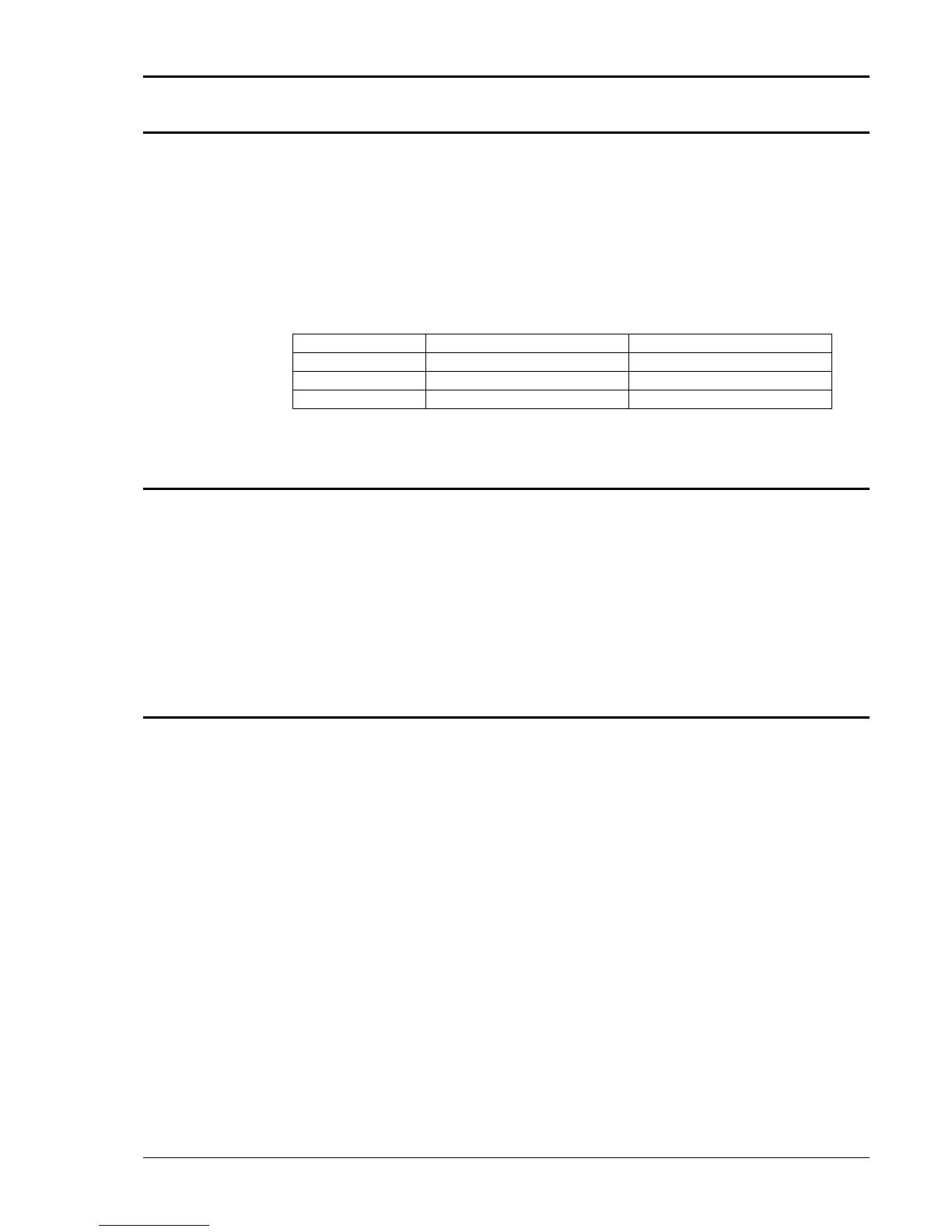
Output Phase Analog Brd Adjustment Adjustment Location
A R25 Right
B R85 Middle
C R120 Left
Table 5-3: AC/DC Zero Adjustment
5.4.3 DC Function DC Zero Adjustment
1. Program the Output DC function, the High Voltage Range and enable the OUTPUT. To
show the OUTPUT CALIBRATION screen for the first time, choose OUTPUT CAL from
the MENU screen. Type 5000 as the password. Press the PHASE key to select the
phase to be calibrated.
2. Program zero VDC and make the adjustments in the OUTPUT CALIBRATION screen
with the Front Panel encoder or keypad. Adjust for ≤ 0.005 VDC.
3. Repeat step 3 for each output phase.
5.4.4 Output Adjustment:
This calibration will only affect the output voltage settling time. It sets the ALC or voltage servo to
the center of its corrections range. Connect the test equipment to the power source as shown in
Figure 6-1. Do not connect the load for the following adjustment. The AC output calibration does
not require an AC DVM operating with the highest accuracy. The numeric value for the
calibration range is from 0 to 65535.
Proceed as follows:
1. Cycle the Input Circuit breaker. Turn OFF the ALC. Program the High Voltage range and
200 volts for each phase.
2. Monitor the Phase A output voltage with the External DVM. Measure the voltage from
the Phase A to the Neutral output terminals.
3. If the Phase A output voltage is not 200 ±1 volts press the MENU key several times to
display the OUTP CAL screen selection and press the ENTER key.
4. Enter the calibration password, CAL PWORD, of 5000 and press ENTER.
5. Adjust the VOLT FS for Phase A to make the external voltage 200 ±1 volts. This must
be done separately for each phase.
6. Repeat step 2 through 5 for the Phase B and C outputs.

 Loading...

