User Manual California Instruments
CSW Series 77
VOLT REF The three program options are INT, EXT and RPV. The INT is
selected for the normal internal reference for program voltage
and frequency. EXT is selected to enable the external signal
input. The signal input can be any waveform from 0 to 5.00
Vrms for a 0 to full-scale Vrms output. The RPV mode is the
external gain control. A 0 to 7.07 VDC input will control the
programmed output waveform from 0 to full-scale Vrms.
NO. OUTPUT This allows the number of output phases to be toggled between
single and three-phase mode. In single-phase mode, all power
from all three outputs is in phase. The three outputs must be
wired together. All programming is for the Phase A function in
the 1-phase mode.
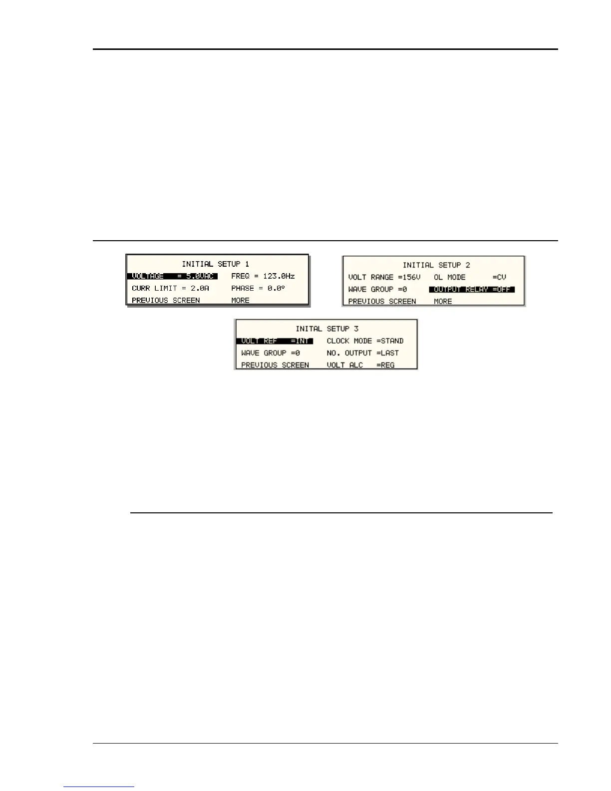
3.11.11.3 INITIAL SETUP menu
Figure 3-29: INITIAL SETUP menus
Any time the AC source is powered up, the output will reflect the values stored as the INITIAL
setup values. This allows the unit to be powered up in a known state at all times. The INITIAL
values can be set in the INITIAL SETUP menus.
The initial setup can be used to power up the AC source with the output on and a high voltage
present at the output. For normal situations, this is not recommended due to the potential
danger to the operator. It is recommended that the initial voltage be set low and/or the output
relay be programmed to OFF for most situations.
The following fields are provided in the INITIAL SETUP menus:
Entry Description
INITIAL SETUP 1
VOLTAGE Sets the power-on AC voltage for AC and AC+DC modes or the
DC voltage for DC mode.
CURR LIMIT Sets the power-on current limit value.
FREQ Sets the power-on frequency value.
PHASE Sets the power-on frequency for phase A with respect to an
external sync signal. If the internal oscillator is used (default)
this setting has no effect.
INITIAL SETUP 2
VOLT RANGE Sets the power-on voltage range value. The available choices
are determined by the VOLT PAIR selected in the
VOLTAGE/CURRENT CONTROL SETUP menu.

 Loading...

