User Manual California Instruments
CSW Series 121
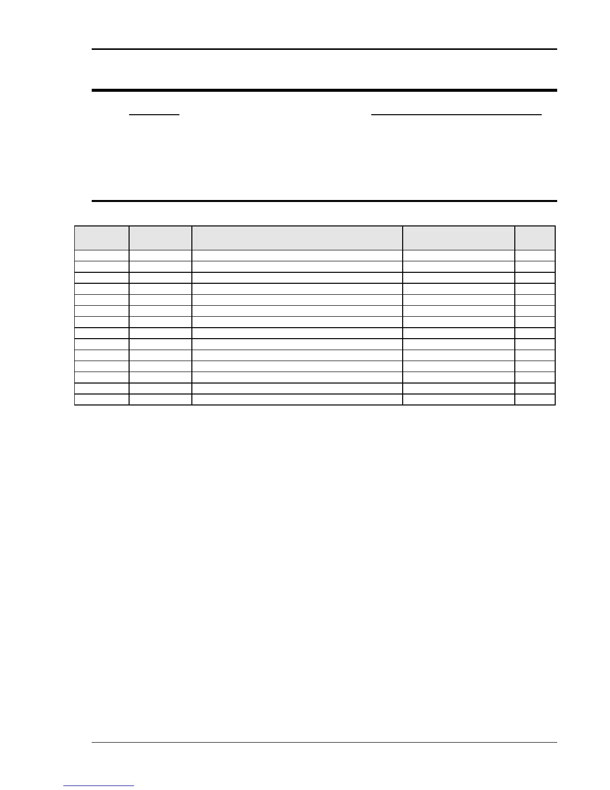
7. Top Assembly Replaceable Parts
Top Assy. Model
7006-404-2 CSW5550, 400 VAC INPUT
7006-404-1 CSW5550, 208 VAC INPUT
7.1 Sub assemblies
# CI PART # DESCRIPTION VENDOR QTY
7006-405-1 Front Panel Assembly (A1, A2, A3 and A4) CI 1
A1 7006-716-1 Display/ Keyboard Assembly CI 1
A2 7006-714-1 Controller Assembly CI 1
A3 5162062-01 Analog Board Assembly CI 1
A4 7006-717-1 BNC Board Assembly CI 1
A5 5162052-01 Circuit Breaker & Trip for 400V CI 1
A5 5162052-02 Circuit Breaker & Trip for 208V CI 1
A7 7006-715-1 Remote Interface Assembly CI 1
A7 7006-715-2 Remote Interface Assembly with LAN CI 1
A14-A16 516273-03 PFC Module Assembly for 208 VAC Line Input CI 3
A14-A16 516273-04 PFC Module Assembly for 400 VAC Line Input CI 3
A17-A19 5161274-05 Amplifier Module Assembly
B1, B2 241183 FAN 6 INCH--JD24B2 Rotron 2
Table 7-1: Replaceable Parts

 Loading...

