User Manual California Instruments
130 CSW Series
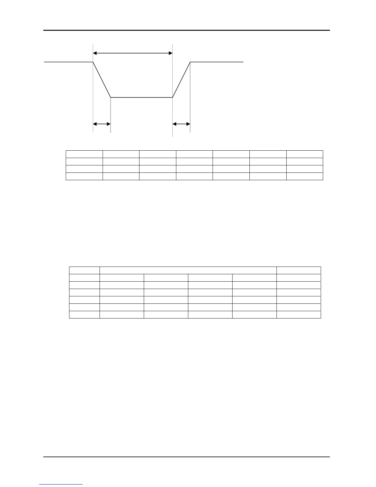
T1
0 Volt
F1 F2
T2 T3
Test no. 21(I) 22(II) 23(III) 24(IV) 25(V) 26(VI)
T1 (ms) 50 50 100 100 200 200
F1 (Hz) 360 Fmax 360 Fmax 360 Fmax
F2 (Hz) Fmax 360 Fmax 360 Fmax 360
Fmax = 650 Hz for Group 2
Fmax = 800 Hz for Group 3
T2 = 20 msec
T3 = 5 msec
Figure 8-7: Power Interrupt for Group 2 and 3
VOLTAGE SURGE
This test requires 160 volts output. If the power source is set at the low voltage range, the high
voltage range will be selected before the test starts. At the end of the test, the power source will
be switched back to the low range automatically
Voltage Time
Seq. No. RTCA Group 1 Group 2 Group 3 ALL
1 115 115 115 115 5 Minute
2 160 160 160 170 30msec
3 115 115 115 115 5 Sec.
4 60 70 70 70 30msec
5 115 115 115 115 5 Sec.
Table 8-4: Normal VoltageSurge Sequence
The output voltage will follow the sequence in Table 8-4. The above sequence will repeat itself
three times. Each repeat will start from sequence two. US and Group 1 will run at 400 Hz.
Group 2 and Group 3 will run at 360 Hz and 650 Hz for Group 2 and 800 Hz for Group 3. The
frequency will return to the nominal setting when the test is completed. The key (backspace)
will terminate the test at any time.

 Loading...

