User Manual California Instruments
CSW Series 31
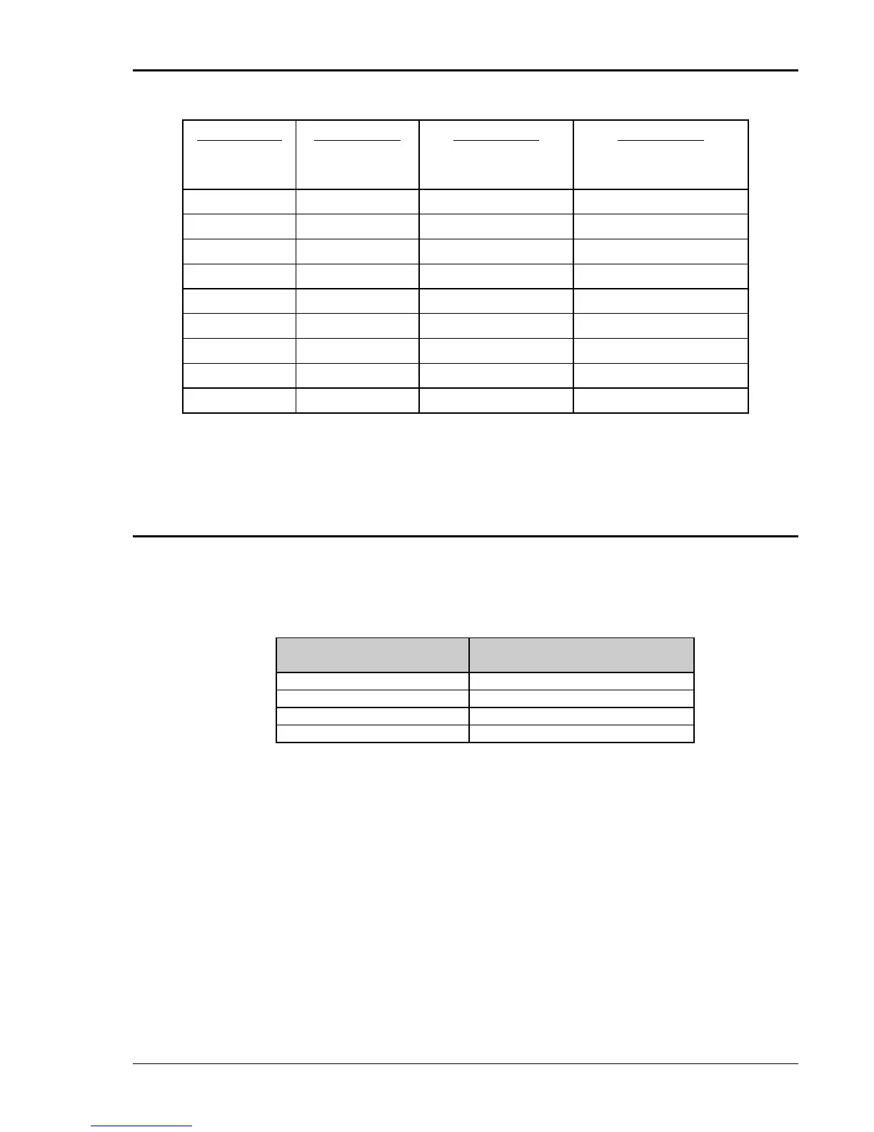
COLUMN 1:
SIZE
(AWG)
COLUMN 2:
AMPERES
(MAXIMUM)
COLUMN 3:
OHMS/100 FEET
(ONE WAY)
COLUMN 4:
IR DROP/100 FEET
(COL. 2 X COL. 3)
14 15 0.257 3.85
12 20 0.162 3.24
10 30 0.102 3.06
8 40 0.064 2.56
6 55 0.043 2.36
4 70 0.025 1.75
2 95 0.015 1.42
1/0 125 0.010 1.25
3/0 165 0.006 1.04
Recommended Wire Gauge Selection Guide
The output power cables must be large enough to prevent a total voltage drop exceeding 1% of
the rated output voltage between the power source and the load. Table 3-1 shows the AWG size
of the cables that may be used. Cable lengths must not exceed twenty-five (25) feet. For lengths
greater than 25 feet, calculate the voltage drop from the following formula:
2 X DISTANCE X CABLE RESISTANCE PER FT. X CURRENT = VOLT DROP
LOAD CURRENT WIRE GAGE
22 AMPS 10 AWG
37 AMPS 8 AWG
74 AMPS 4 AWG
111 AMPS 2 AWG
Table 3-1: Wire Sizes

 Loading...

