User Manual California Instruments
CSW Series 85
3.13 Waveform Management
The CSW Series employs independent arbitrary waveform generators for each phase. This
allows the user to create custom waveforms. In addition, the CSW offers three standard
waveforms that are always available. This chapter covers issues that relate to defining,
downloading and managing custom waveforms.
3.13.1 Standard Waveforms
For many AC applications, a sine wave shape is used. The sine wave is one of the standard
waveforms provided on the CSW Series. The standard sine wave is always available and is the
default waveform at power-on. In addition to the sine wave, two more standard waveforms are
available, square and clipped.
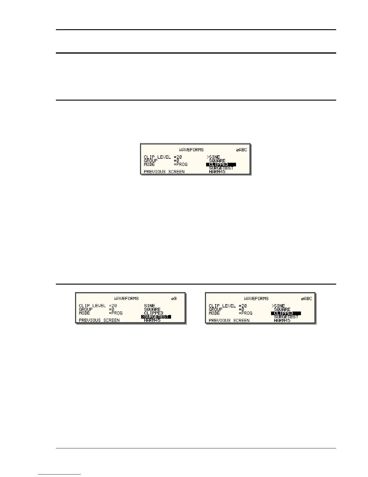
Figure 3-34: Selecting a waveform
The square wave provides a high frequency content waveform with relative fast rise and fall
times. Due to AC amplifier bandwidth limitations, the frequency content of the standard square
wave has been kept within the amplifier’s capabilities. As the fundamental frequency is
increased, the relative contribution of higher harmonics is reduced.
The clipped sine wave may be used to simulate voltage distortion levels to the unit under test.
The total harmonic distortion level may be programmed in percent using the CLIP LEVEL field of
the WAVEFORMS menu. Changing the distortion level of the CLIP waveform forces the AC
source to regenerate the CLIPPED sine wave’s data points and reload the waveform register
with the newly requested data. This process requires the output to be dropped briefly. To avoid
interrupting the voltage output to the unit under test, select a different waveform such as the
standard sine wave first, change the clip level and change the waveform back to the CLIPPED
sine wave. This will avoid any output interruption.
3.13.2 Phase Selection
Figure 3-35: Selecting waveforms for single phase or all phases
Different waveforms may be selected for each phase. The number of custom waveforms from
which to select remains 50 but each phase can be assigned a different custom or standard
waveform. The specific output phase for which the wave shape is programmed is selected with
the PHASE key on the front panel. The selected phase is always shown in the top right hand
corner of the WAVEFORMS display.
To select the same wave shape for all three phases in a three phase configuration, press the
PHASE key until the øABC enunciator appears in the top right corner of the WAVEFORMS
menu. Waveform selections made in this mode will apply to all three phases.

 Loading...

