User Manual California Instruments
34 CSW Series
3.6.3 RS232C Serial Interface Connector
Pin Name Direction
1 N/C
2 TxD Output
3 RxD Input
4 N/C
5 Common Common
6 N/C
7 CTS Input
8 RTS Output
9 N/C
Table 3-3: RS232 Connector pin out
The CSW series power sources use a regular straight-through DB9 male to DB9 female serial
cable for the RS232 interface.
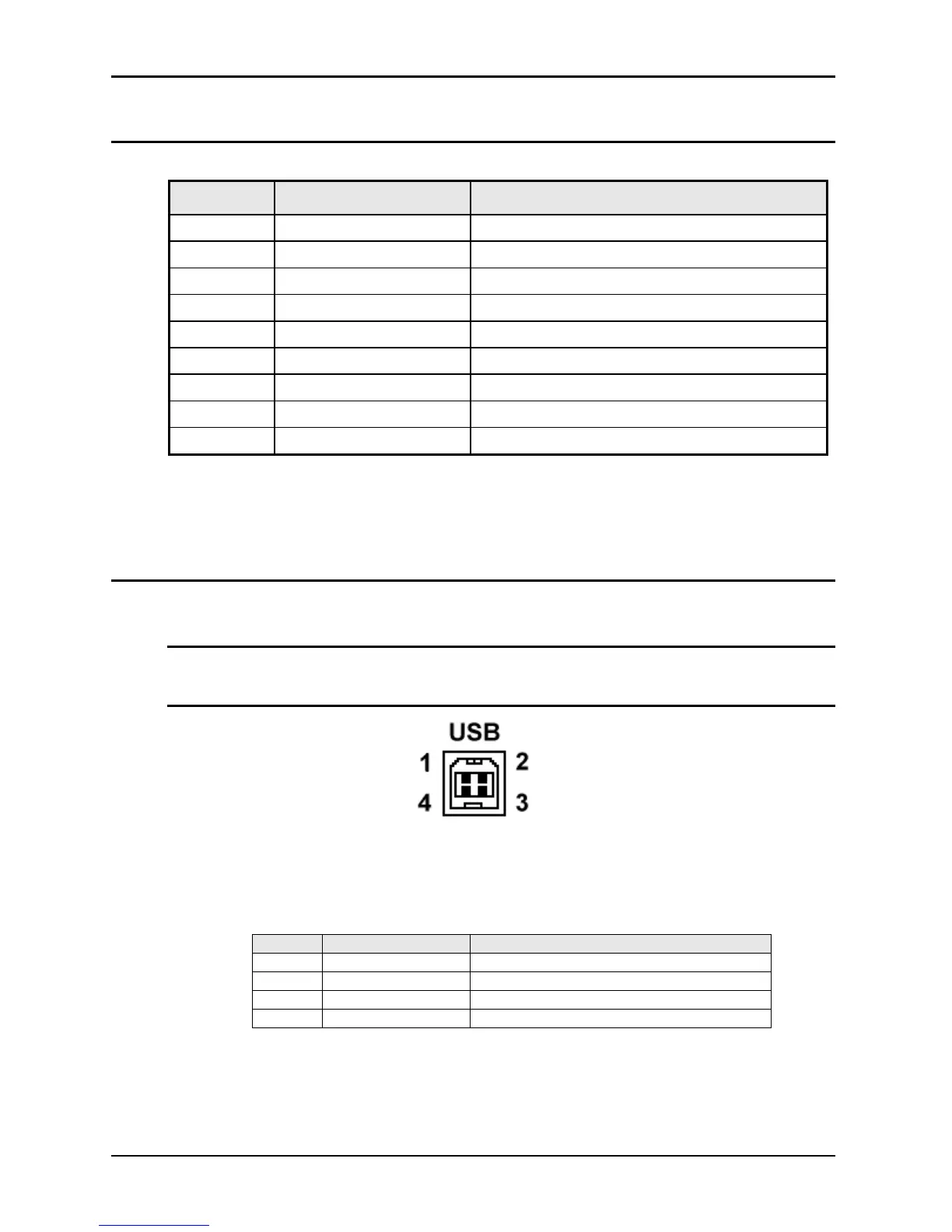
3.6.4 USB Interface
A standard USB Series B device connector is located on the rear panel for remote control. A
standard USB cable between the AC Source and a PC or USB Hub may be used.
Note: Use of the USB port to control more than one power source from a single PC is not
recommended, as communication may not be reliable. Use GPIB interface for
multiple power source control.
Figure 3-2:USB Connector pin orientation
Pin Name Description
1 VBUS +5 VDC
2 D- Data -
3 D+ Data +
4 GND Ground
Table 3-4: USB Connector pin out.

 Loading...

